2
03.11
-
-
-
-
TOR.119.--.M.4L Rev. A1
VAR
1
3
2
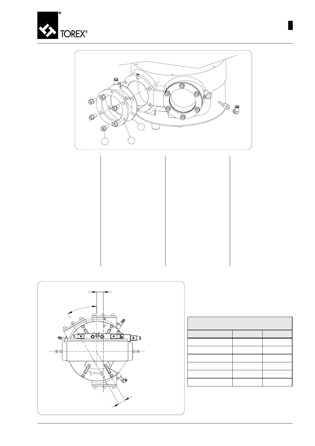
Fig. 8
1) Saldare i tre imbocchi per tubi
(controflange) (pos. 1, fig. 8)
comprese nella fornitura, al
tubo di arrivo materiale e ai
due tubi di uscita materiale.
2) Imbullonare poi i tre imbocchi
per tubi (pos.1, fig.8) utiliz-
zando i bulloni (pos.2 fig. 8) e
la guarnizione (pos. 3, fig. 8)
alle rispettive aperture del
deviatore.
IMPORTANTE:
La valvola deviatrice VAR NON
può essere impiegata da
sostegno esterno per altre
macchine sottostanti
(coclee, nastri, trasportato-
ri, estrattori ecc..).
1) Souder les trois embouts pour
tubes (contre-bride) (pos. 1,
fig. 8) inclues dans la fourni-
ture, au tube d’arrivée matiè-
re et aux deux tubes de sor-
tie matière.
2) Puis boulonner les trois em-
bouts (pos.1, fig.8) en utili-
sant les boulons (pos.2 fig.
8) et le joint (pos. 3, fig. 8)
aux ouvertures respectives
de la vanne déviatrice.
IMPORTANT:
La vanne déviatrice VAR NE
PEUT PAS être utilisée com-
me support extérieur
d’autres machines placées
dessous (vis sans fin, ban-
des, convoyeurs, extrac-
teurs etc..).
1) Die drei Anschlüsse für die
Rohre (Gegenflansche) (Pos.
1, Abb. 8), die zum Lieferum-
fang gehören, an dem Ein-
laufrohr des Materials und an
den beiden Auslaufrohren
des Materials anschweißen.
2) Dann die drei Anschlüsse für
die Rohre (Pos.1, Abb. 8) mit
den Schrauben (Pos.2 Abb.
8) und der Dichtung (Pos. 3,
Abb. 8) an den entsprechen-
den Öffnungen der Rohrwei-
che verschrauben.
WICHTIG:
Die Rohrweiche VAR darf
NICHT als externe Stütze für
andere Maschinen darunter
benutzt werden (Schne-
cken, Bänder, Fördervorrich-
tungen, Austragseinrichtun-
gen etc.).
1) Weld the three inlets for tubes
(counter flanges) (pos. 1, Fig.
8) included in the supply to
the material inlet tube and the
two material outlet tubes.
2) Then bolt the three inlets for
tubes (pos.1, Fig.8) using
bolts (pos.2 Fig. 8) and the
gasket (pos. 3, Fig. 8) to the
relative openings of the di-
verter valve.
IMPORTANT:
The VAR diverter valve CAN-
NOT be used as an external
support for other machines
underneath (screw convey-
ors, conveyor belts, convey-
ors, extractors etc...).
MISALIGNMENT OF THE OUTLET SPOUTS - VERSATZ DER AUSLAUFÖFFNUNGEN
DESALIGNEMENT DES BOUCHES DE SORTIE - DISALLINEAMENTO DELLE BOCCHE DI USCITA
3
0
°
J
N
Fig. 9
Misalignment - Versatzwinkel
Désalignement - Disallineamento
Type N J
VAR80
33 33
VAR100
39 39
VAR125
46 46
VAR150
52 52
VAR175
60 60
VAR200
64 64
17
INSTALLATION – MECHANICAL CONNECTIONS
INSTALLATION - MECHANISCHE ANSCHLÜSSE
INSTALLATION - RACCORDEMENTS MÉCANIQUES
INSTALLAZIONE - COLLEGAMENTI MECCANICI
 Loading...