Do you have a question about the WAMGROUP TOREX VAR 100 and is the answer not in the manual?
Step-by-step guide for starting the diverter valve operation.
Details procedures for maintaining the diverter valve.
Lists common issues and their solutions for troubleshooting.
Primary list of essential spare parts with their codes and quantities.
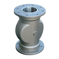
Explains the intended use of VAR diverter valves for conveying products.
Lists conditions and materials for which VAR Diverter Valves are not designed.
Specifies the operational temperature ranges for fluid and environment.
Details the operating pressure limits for the diverter valve and its components.
Highlights safety regulations for operators and emphasizes strict adherence.
Prohibits use by unauthorized personnel and assigns responsibility for operator training.
Ensures correct product usage and maintenance of attached safety notices.
Details procedures for safe operation, including disconnection and protective equipment.
Lists actions strictly forbidden during operation, maintenance, or repair.
Specifically forbids inserting hands or objects into valve outlets or spouts.
Prohibits partial use by unauthorized personnel and emphasizes proper training.
Ensures correct product use, maintenance, and use of protective equipment.
Details electrical safety, disconnection, and compliance with relevant directives.
Installer must provide and install safety measures to prevent damage and harm.
Installer must perform functional check and adjustment of the diverter valve.
Details connecting the valve to pneumatic and electric circuits, checking pressure and voltage.
Details pneumatic connections for diverter valves with actuators and bare shafts.
Crucial safety check: ensure valve operation causes no harm to personnel or machinery.
Ensures machine is made safe before commencing start-up operations.
During initial start-up, monitor for anomalies like noise, irregular rotations, or vibrations.
Perform a safety check before switching off the valve and ensure it is completely empty.
Procedure for switching conveyor lines, including closing flows and deflating seals.
Critical instruction to cut power to seals solenoid before switching lines for safety.
Ensures machine and plant are made safe before any maintenance operation.
Operator must use PPE and reach work points safely.
Warns against working inside the valve and mandates disconnecting power.
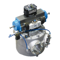
Step-by-step instructions for dismantling the pneumatic actuator from the diverter valve.
Install the pneumatic actuator onto the diverter valve, inserting the drive pin.
Mount the solenoid valve in its actuator seat following provided instructions.
Lubricate seals and position solenoid valve correctly onto actuator.
Secure the solenoid valve to the actuator using the provided screws.
Connect unions to the solenoid valve for inflatable seals using provided fittings.
Insert 90° unions into air unions to supply air to inflatable seals.
Connect the actuator solenoid valve to the air line and electrical supply.
Connect the two actuator solenoids to the electrical line, checking voltage.
Pressurize valve in I-O position, adjust screw to align drum passage to outlet.
Verify drum passage tube alignment with LH outlet spout (I-O position).
Verify drum passage tube alignment with RH outlet spout (I-X position).
Switch lines between I-X and I-O positions multiple times, checking alignment.
Tighten all adjuster screws after achieving perfect alignment.
Ensure machine is safe before starting any work on the micro switch box.
Disconnect electrical supply before connecting or maintaining the apparatus.
Prohibits removing the cover while the equipment is powered.
Perform calibration and adjustment before using the micro switch box.
Cut electrical supply from the circuit before disassembling the micro switch box.
Remove cover, gasket, and disconnect electrical supplies from terminal boards.
Remove screws fixing the box body to brackets, then remove the box and brackets.
Ensure safety and remove cover, gasket, and disconnect internal supplies.
Remove direction indicator and rotate actuator anticlockwise to I-O position.
Manually rotate lower cam to activate lower limit switch for I-O passage.
Rotate actuator clockwise to I-X position, referring to the general connection diagram.
Manually rotate upper cam to activate upper limit switch for I-X passage.
Connect electricals for limit switches signalling I-X and I-O positions.
Ensure machine is safe before commencing any cleaning operations.
Addresses issues with the diverter valve not switching or switching slowly.
Troubleshoots material presence in the body, air leaks, and seal failures.
Details electrical risks, connections, and earthing requirements for safe operation.
Warns about high surface temperatures and the need for operator protection.
Mandates the use of gloves as a compulsory safety measure.
Mandates the use of masks as a compulsory safety measure.
Offers a catalogue of spare parts for the diverter drum.
| Brand | WAMGROUP |
|---|---|
| Model | TOREX VAR 100 |
| Category | Control Unit |
| Language | English |