2
TOR.119.--.M.4L Rev. A1
03.11
-
-
-
-
VAR
26
3
22
MAINTENANCE – INFLATABLE SEALS VALVE ASSEMBLY
WARTUNG - EINBAU DES VENTILS DER AUFBLASBAREN DICHTUNGEN
ENTRETIEN - MONTAGE VANNE JOINTS GONFLABLES
MANUTENZIONE - MONTAGGIO VALVOLA TENUTE GONFIABILI
INFLATABLE SEALS VALVE ASSEMBLY - EINBAU DES VENTILS DER AUFBLASBAREN DICHTUNGEN
MONTAGE VANNE JOINTS GONFLABLES - MONTAGGIO VALVOLA TENUTE GONFIABILI
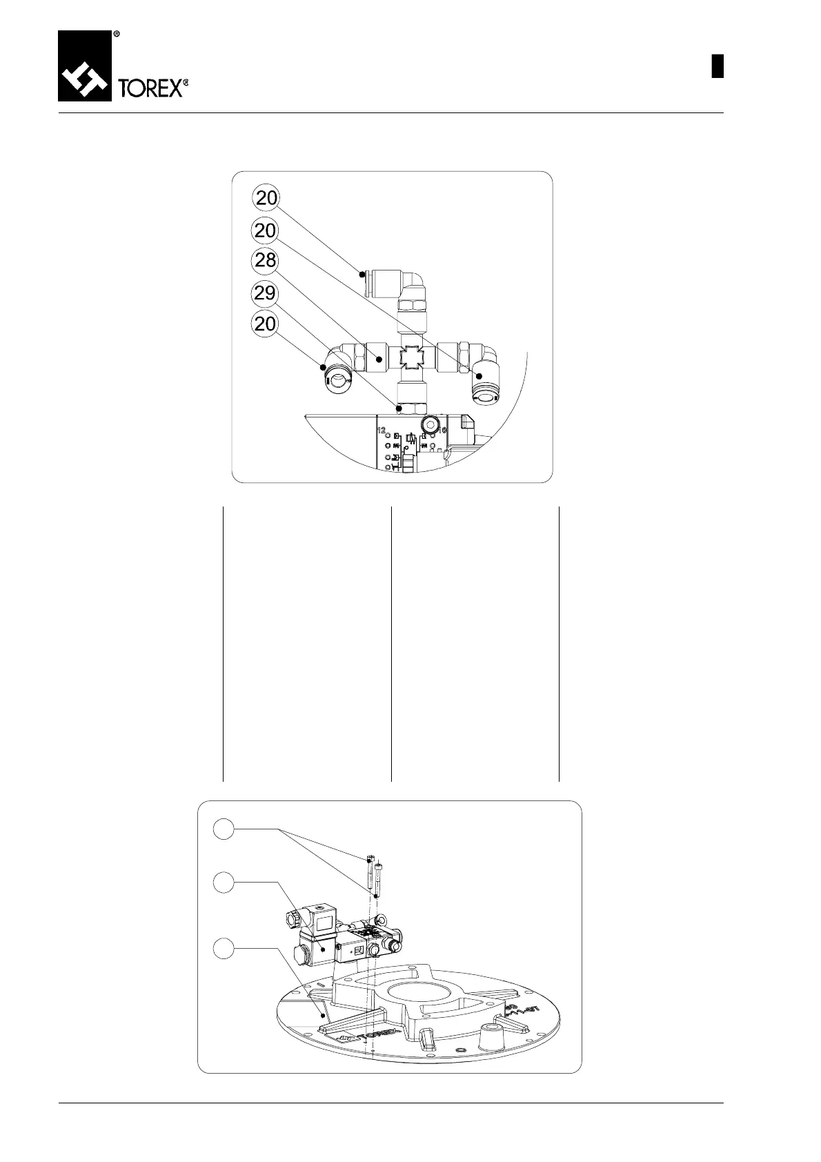
Fig. 43
Per il montaggio della valvola a
solenoidi per le tenute gonfiabili
procedere nel seguente modo:
1) Inserire il Nipplo Conico 1/8”
M – 1/8” M (pos. 29, fig. 43)
avvitandolo all’utilizzo 2 (usci-
ta) della valvola a solenoidi
(vedi “DIAGRAMMA ELET-
TROVALVOLE PER GON-
FIAGGIO TENUTE)
2) Avvitare al Nipplo Conico 1/
8” M – 1/8” M (pos. 29, fig.
43) il Raccordo a Croce 1/8”
F (pos. 28, fig. 43)
3) Inserire i 3 Raccordi 90° 1/8”
per tubo diam. 6 mm (pos. 20,
fig. 43) nei 3 attacchi filettati
del Raccordo a Croce.
Fig. 44
Pour le montage de la vanne à
solénoïdes pour les joints gon-
flables procéder de la manière
suivante :
1) Introduire le raccord Nipple
Conique 1/8" M – 1/8" M (pos.
29, fig. 43) en le vissant au
point d’utilisation 2 (sortie) de
la vanne à solénoïdes (voir
“DIAGRAMME ELECTROVAN-
NES DE GONFLAGE JOINTS).
2) Visser au raccord Nipple Co-
nique 1/8" M – 1/8" M (pos.
29, fig. 43) le Raccord en
croix 1/8 » F (pos. 28, fig.
43).
3) Introduire les 3 Raccords 90°
1/8" pour tube diam.6 mm
(pos. 20, fig. 43) dans les 3
attaches filetées du Raccord
en Croix.
Für den Einbau des Magnetven-
tils für die aufblasbaren Dichtun-
gen ist wie folgt vorzugehen:
1) Den Kegelnippel 1/8" M – 1/8"
M (Pos. 29, Abb. 43) einste-
cken, indem man ihn am Ver-
braucher 2 (Ausgang) des
Magnetventils anschraubt
(siehe “DIAGRAMM MAG-
NETVENTILE ZUM AUFBLA-
SEN DER DICHTUNGEN”)
2) Am Kegelnippel 1/8" M – 1/8"
M (Pos. 29, Abb. 43) den
Kreuzanschluss 1/8" F (Pos.
28, Ab. 43) anschrauben.
3) Die 3 Übergangswinkel 90° 1/
8" für Rohr Durchmesser 6
mm (Pos. 20, Abb. 43) in die 3
Gewindeanschlüsse des
Kreuzanschlusses stecken.
To assemble the inflatable seals
solenoid valve, proceed as de-
scribed below:
1) Insert the 1/8" M – 1/8" M Ta-
per Nipple (pos. 29, Fig. 43)
screwing it to utility point 2
(outlet) of the solenoids valve
(see “SEALS INFLATION SO-
LENOID VALVES DIAGRAM)
2) Screw the 1/8" F Cross con-
nector (pos. 28, Fig. 43) to
the 1/ 8" M – 1/8" M Taper
Nipple (pos. 29, Fig. 43)
3) Insert the three 90° 1/8" Un-
ions for the diam. 6 mm tube
(pos. 20, fig. 43) in the three
threaded unions of the Cross
Connector
46
 Loading...