Service Manual
OLP-101-15
Soldering SMDs into position
-
SMDs without pins
Use hot gas. The solder must be flowing on both pads simultaneously.
-
SMDs with pins
Use a miniature soldering iron or hot gas. Diagonally opposite IC pins must be soldered
alternately.
-
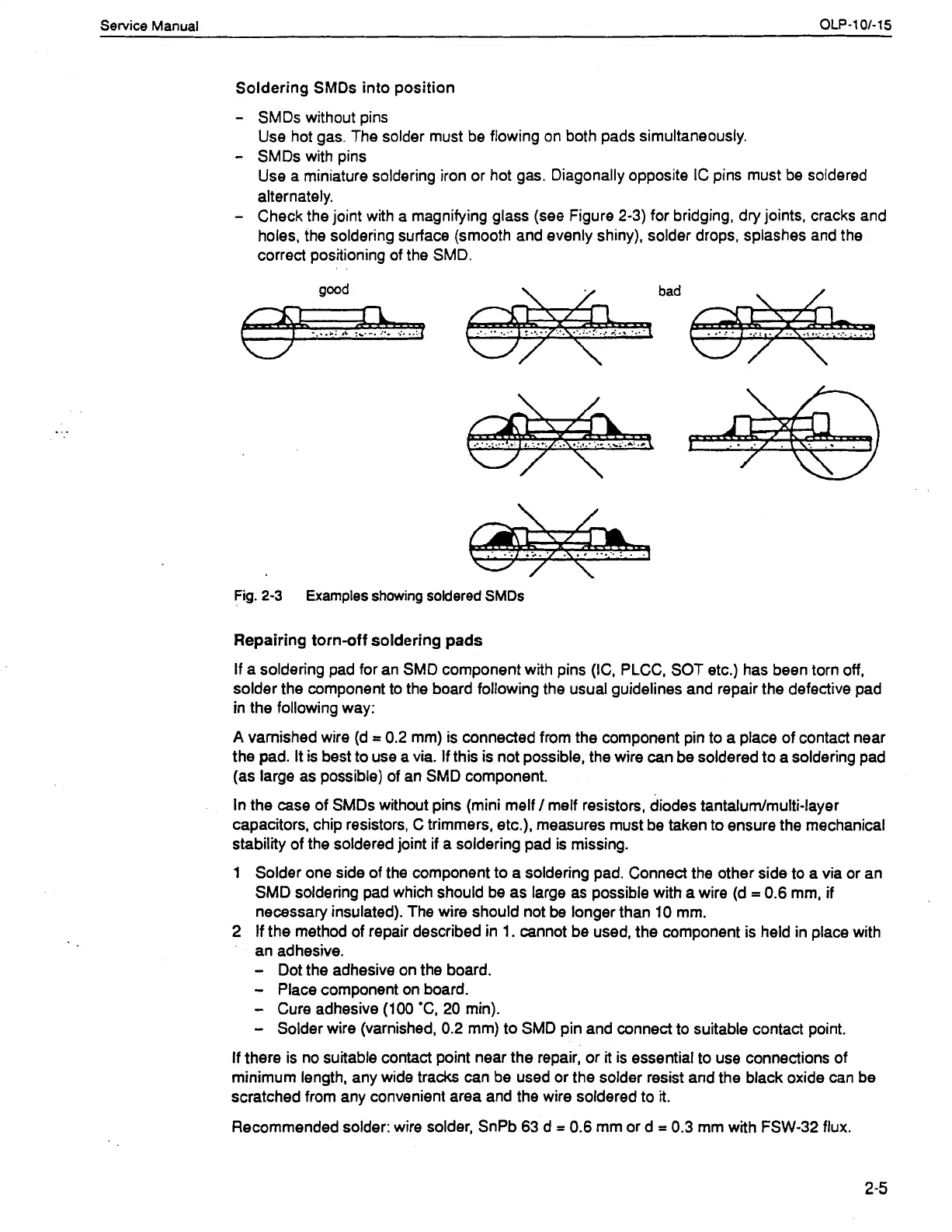
Check the joint with a magnifying glass (see Figure 2-3) for bridging, dry joints, cracks and
holes, the soldering surface (smooth and evenly shiny), solder drops, splashes and the
correct positioning of the SMD.
\
bad
Fig.
2-3
Examples showing soldered SMDs
Repairing torn-off soldering pads
If a soldering pad for an SMD component with pins (IC, PLCC, SOT etc.) has been torn off,
solder the
component to the board following the usual guidelines and repair the defective pad
in the following way:
A
varnished wire (d
--
0.2 mm) is connected from the component pin to a place of contact near
the pad. It is best to use a via. If this is not possible, the wire can be soldered to a soldering pad
(as large as possible) of an SMD component.
In the case of SMDs without pins (mini melf
/
melf resistors, diodes tantalurn~multi-layer
capacitors, chip resistors, C trimmers, etc.), measures must be taken to ensure the mechanical
stability of the soldered joint if a soldering pad is missing.
1 Solder one side of the component to a soldering pad. Connect the other side to a via or an
SMD soldering pad which should be as large as possible with a wire (d
=
0.6 mm, if
necessary insulated). The wire should not be longer than 10 mm.
2 If the method of repair described in 1. cannot be used, the component is held in place with
an adhesive.
-
Dot the adhesive on the board.
-
Place component on board.
-
Cure adhesive (100 'C, 20 min).
-
Solder wire (varnished, 0.2 mm) to SMD pin and connect to suitable contact point.
If there is no suitable contact point near the repair, or it is essential to use connections of
minimum length, any wide tracks can be used or the solder resist and the black oxide can be
scratched from any convenient area and the wire soldered to
it.
Recommended solder: wire solder, SnPb 63 d
=
0.6
rnm or d
=
0.3 mm with FSW-32 flux.
Artisan Technology Group - Quality Instrumentation ... Guaranteed | (888) 88-SOURCE | www.artisantg.com
 Loading...