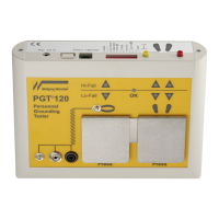
PGT
®
120.COM Art.Nr. 7100.PGT120.COM
6 / 17 2016-09-07
4 Operation
This tester has no power switch. Connecting the power supply activates the electrical
circuit.
The measuring voltage is preset to 100V. Use the DIP switches 6+7 to adjust the
voltage to either 30V or 50V.
4.1 Wrist strap test
Only wrist strap or OR is activated (DIP switch 1+2; RS232)
Put on the wrist strap and connect it via a coil cord to the snap or to the socket on the
left side of the unit.
Press the left electrode and keep it pressed. A peep signal indicates the start of
measurement. After a short measuring time the result is displayed.
The measured value is o.k.
Red LED flashes,
audible signal
Above the resistance upper limit
Red LED flashes,
audible signal
Below the resistance lower limit
(not applicable if lower limit is disabled)
Release the electrode.
4.2 Coil cord test
Only wrist strap or OR is activated (DIP switch 1+2; RS232)
To check only the coil cord, connect the coil cord to the 3mm snap located inside the
wrist strap symbol and to the 10mm snap or socket on the left side of the unit.
Press the left electrode and keep it pressed. A peep signal indicates the start of the
measurement. After a short measuring time the result is displayed.
The measured value is o.k.
Red LED flashes,
audible signal
Above the resistance upper limit
Red LED flashes,
audible signal
Below the resistance lower limit
(not applicable if lower limit is disabled)
 Loading...