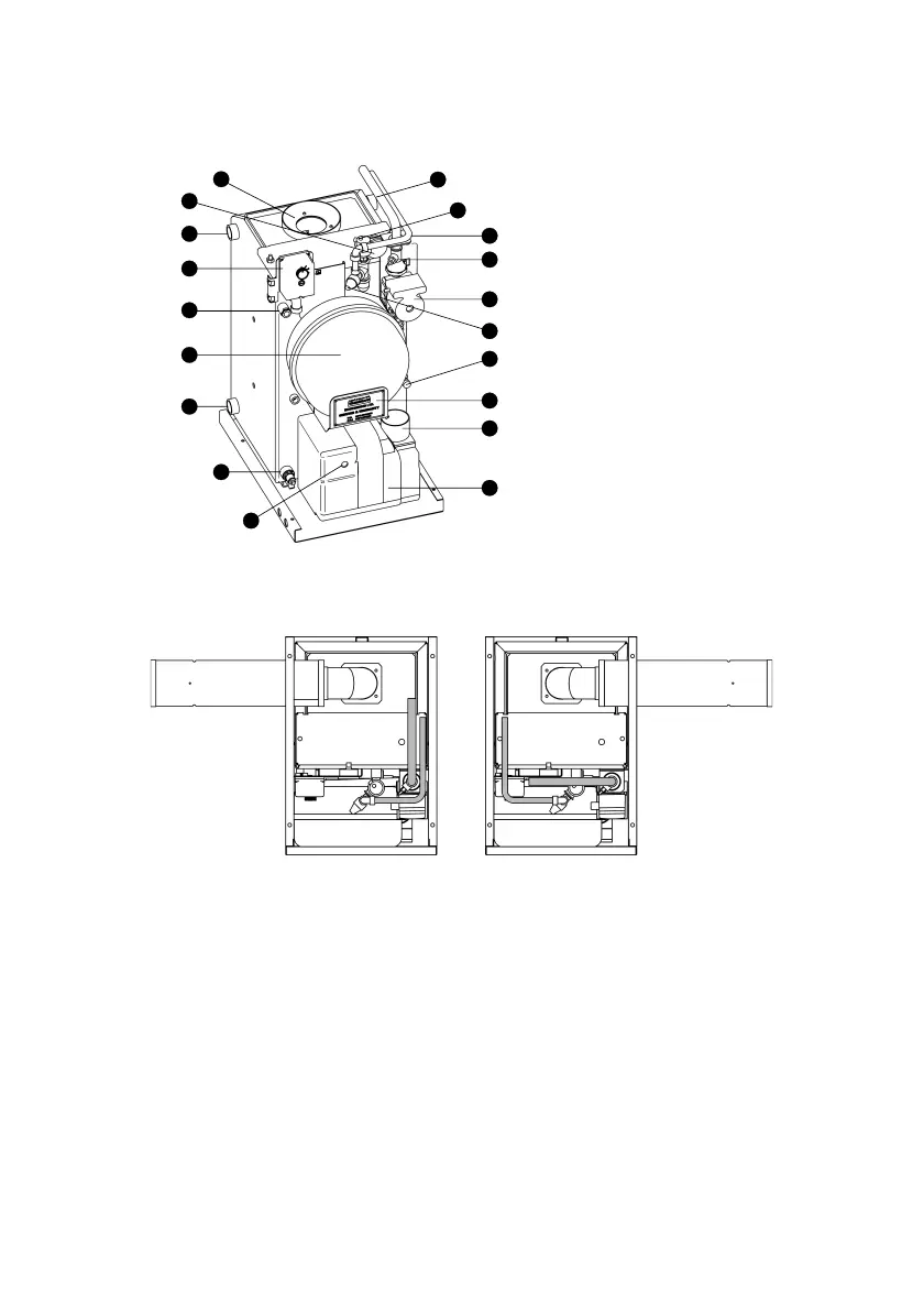
1 Flue
2 System Pressure Gauge
3 Spare BSP Connection (x2)
4 Boiler Limit Thermostat
5 Thermostat Pocket
6 12L Expansion Vessel
7 Heating Return (x2) 1” BSP
8 Drain Cock
9 Heating Flow
10 Automatic Air Vent
11 Pressure Relief Discharge
12 Isolation Gate Valve (x2)
13 Grundfoss Pump
14 Pressure Relief Valve
15 Filling Loop Connection
16 Data label
17 Optional Air Intake Spigot
18 RDB Burner
19 Burner Reset Button/Lock Out Lamp
1.5.2 Pipe Layout
1.5.3 Mains Water Supply
The mains water connection for the filling loop has been left free for the installer to fit
a 15mm copper pipe. The pipe can be routed over the top of the boiler, down one of
the side channels or through the cable entry grommets towards the front of the base
tray.
Note: Also our domestic appliances have been independently tested and accredited
as exceeding the minimum SEDBUK efficiency levels required for its type, in
compliance with the Building Regulations Approved Document L1 2001 for
England and Wales and the Building Standards (Scotland) Regulations 2001
Part J.
1.5 System Boiler
1.5.1 Components
18
17
16
15
14
13
12
11
10
9
8
7
6
4
3
2
1
19
5
Page 3
 Loading...