Page 16 of 34
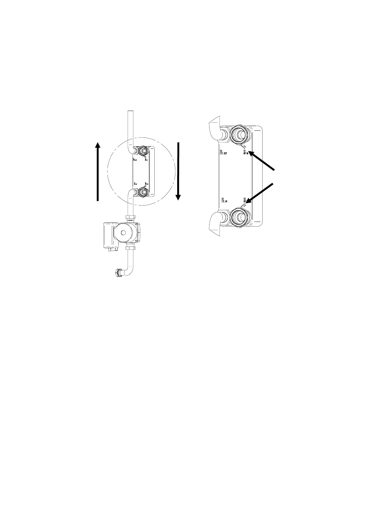
6.8 Plate heat exchanger installation
The plate heat exchanger is of asymmetric design and must be fitted respecting the flow of both
potable and system (Heat Pump) water. See separate assembly document provided with the
HP cylinder kit.
There are orientation marks on the plate heat exchanger, these are to be connected to the
system water circuit.
Figure 5c: Heat Pump model plate heat exchanger connections
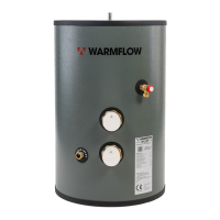
Potable water circulating pump installation
The circulating pump must always be installed with horizontal motor shaft. At start-up, the rotor
can must be vented by removing the plug in the top of the motor. Within a short time, the rotor
forces the remaining air out into the system via the shaft.
The circulating pump must be installed with the flow direction as marked on the pump housing
from the lower connection on the cylinder towards the plate heat exchanger, see Figure 5b for
reference.
The circulating pump must be installed with the terminal box above, or to the left or right side of
the pump.