Page 22 of 34
6.11 Electrical Installation
Note: All wiring activities described in the following sections should only be undertaken
by trained persons having an appropriate level of competency/qualification.
Before proceeding, ensure all electrical supplies to the appliance are verified as isolated
and prevented from accidental reconnection.
220 – 240V. 1PH, 50Hz
The Immersion heater(s), thermostats and other external electrical equipment should be wired
with correctly rated heat resistant cable, isolating switches and fusing.
The appliance must be effectively earthed and all external wiring should comply with
current IEE Regulations.
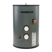
Mount the cylinder thermostat by carefully inserting the capillary sensors into the appropriate
pocket, then secure the thermostat base to the pocket using the provided screws.
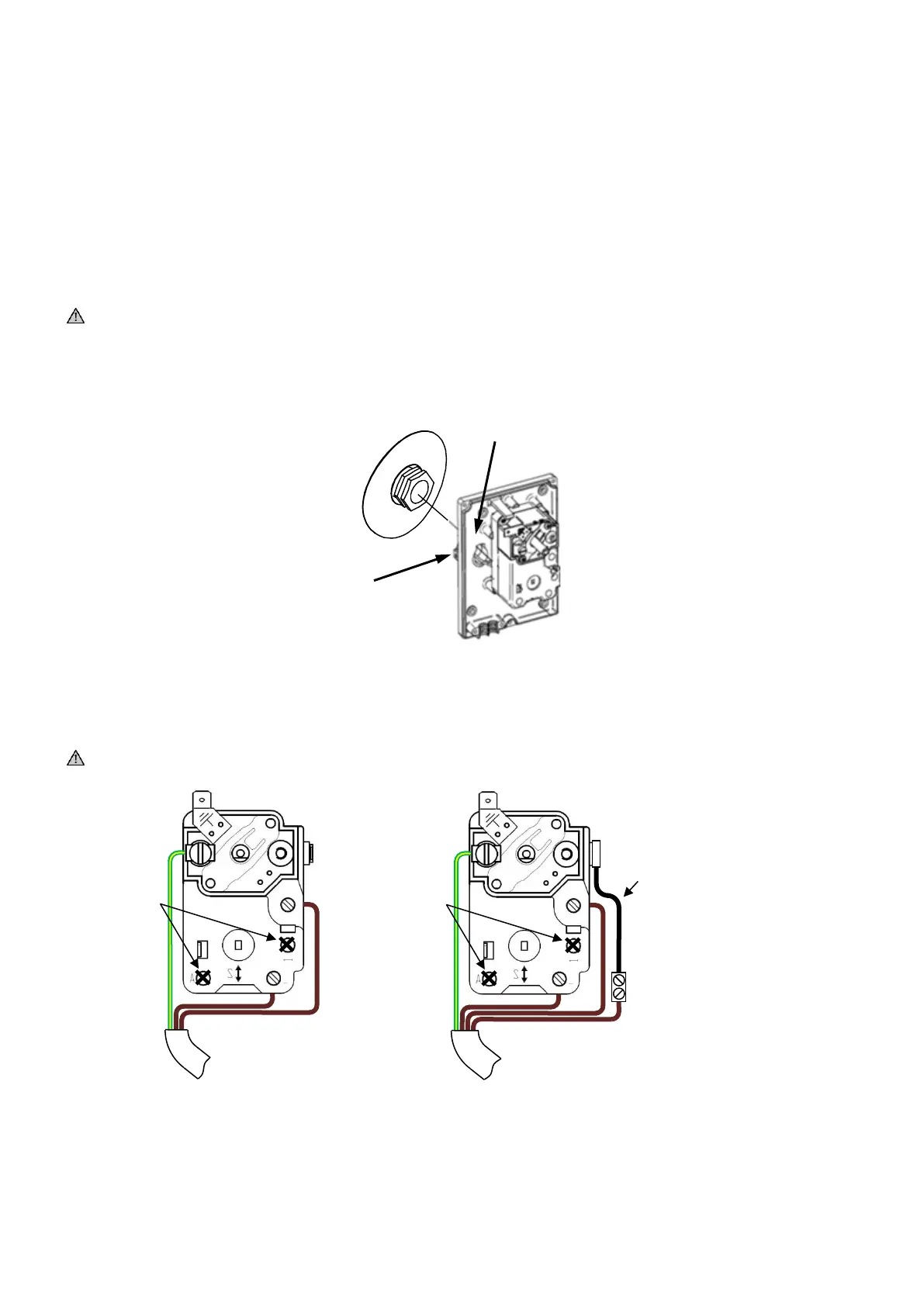
6.11.1 Cylinder Thermostat Wiring
Typical S and Y plan wiring examples are shown in section 6.11.7
Thermostats must be earthed.
Figure 7: Control thermostat wiring