8
warmhaus.com
2.2. COMBI INSTALLATION RULES
2.2.1. General Rules for Installation Places of Combi Boilers
No restrcton s avalable for places where Hermetc (C typ) comb s nstalled
(devces may be nstalled regardless the room volume and ventlaton type).
Also, they may be nstalled at partally protected areas such as balcony,
terrace provded that beng placed n protectve cabnets and takng requred
precautons aganst frost of nstallaton water.
Comb should be soundly nstalled to buldng wall. Flexble connecton
pece should be used between the comb and gas lne. Flex lengths to be
used n A, B and C type devces should not exceed dmensons allowed by
local gas authortes. Flue outputs of hermetc combs must be connected to
places open to exteror and havng ar crculaton. Installaton (postons of
ppe output openng based on varous forms, vertcal, horzontal mnmum
dstances, cross secton areas of channels f gven to channels, etc.) must
be carred out accordng to regulaton standards, current legslaton and
n complance wth local techncal regulatons and the requred techncal
procedures.
2.2.2. Places Not Suitable for Installing Hermetical Combi Boilers
Starways of Buldngs,
• Corrdors avalable for general use, ventlaton ways and shafts, lofts, attcs,
emergency ext doors, cellars, hall and smlar places creatng common use
areas,
• Yards between buldngs,
• Narrow cornce dstances,
• Over flue walls,
• Enclosed balcones,
• Open balcones (except beng located n the cabnet and permsson of the
devce company),
• Below protrudng structure parts preventng exhaust gas output,
• Places those may be drectly subjected to wnd resstance,
• It s forbdden to nstall Hermetc comb (C type) to openngs provdng
clean ar to other unts!
2.2.3. Wall Installation of Combi and Selecting the Installation Place
• It should be controlled and ensured that the wall nstallaton of the comb
s sound and relable.
• The hanger plate gven as standard wth the comb should be nstalled
accordng to the technque to full or sem-full brck wall accordng to
nstallaton scheme and wth connecton screws and not to be used for
other purposes.
• In case of usng derent materals for nstallaton, comb shall be out of
the warranty scope.
• If the wall of nstallaton s not a brck wall, ntally the relablty of support
system should be controlled.
• Comb should be nstalled on a wall resstant to fre.
• NOTICE: Combustble and corrosve materals:
• Chemcally aggressve substances can corrode the applance and
nvaldate any guarantee.
• Do not store or use any combustble materals (paper, thnners, pants,
propellants, cleanng agents etc.) Keep the dstance mnmum 50 mm.
• Insde the cupboard contanng the applance or wthn the vcnty of the
applance.
• 1,8 - 2,2 m heght s recommended for nstallaton of the comb hanger
plate.
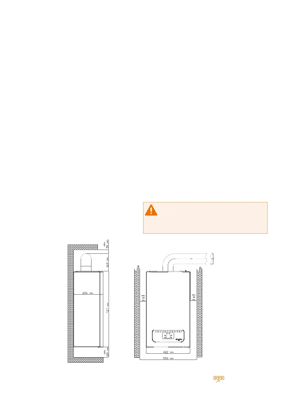
• For places wth lmted nstallaton place, comb should be nstalled
at mnmum 30 cm heght from ground and by leavng at least 5 cm
dstances from both sdes n order to allow easy nterventon of the servce
techncan.
• Comb nstallaton must not performed n envronments contanng
explosve, flammable substances and acd fumes
• Installaton cannot be made at near or on ovens, radators or heater
devces.
• Hermetc combs can be nstalled n furntures but at least 5 cm each
should be left at both sdes.
• If to be nstalled on the ktchen table or the set, at least 30 cm dstance
should be left under the comb.
• It s recommended to connect the output to dran lne wth a transparent
hose aganst the possblty of water leakage from Safety Valve of comb
durng nstallaton. If ths s not possble; do not place electronc devces,
delcate, corrodble devces, components and tools under the comb.
• Do not place/use any furntures below the comb due to above mentoned
reasons.
Make sure that there are no lquds or nflammable materals n the
mmedate vcnty of the boler.
It s necessary to leave a spesfc dstance 1.0 mt between the
heatng devce and the buldng materal contanng combustble materal
even the maxmum allowable temperature value of 85 °C n the rated heat
capacty of the applance s not exceeded.
Fgure 6 Boler mnmum dmensons n the cabnet *Mnmum clearances requred for servcng
 Loading...