©2020 Warn Industries, Inc.WARN® and the WARN logo are trademarks of Warn Industries Inc. 6 107333A0
INSTALLATION INSTRUCTIONS
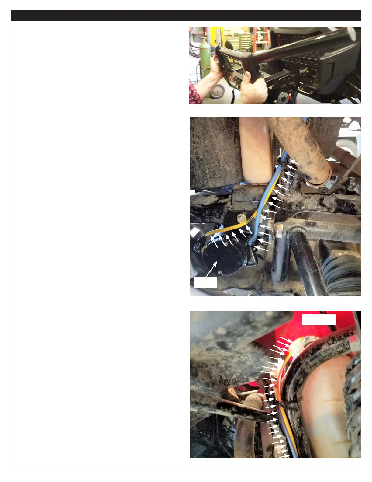
11. Install brush guard/winch assembly to vehicle using
factory hardware.
12. Choose a location to mount the winch contactor. Be sure
the blue and yellow ends are able to reach contactor easily.
13. Mount contactor per winch installation instructions.
14. Route blue and yellow winch power cables along frame
upright tube, towards contactor. Use zip ties to secure
cables to the frame along the way.
15. Route wires through top plastic continuing to use cable
ties to secure wires.
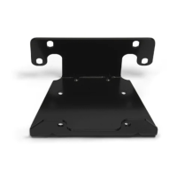
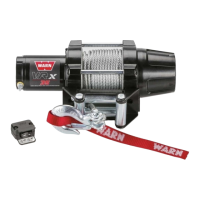
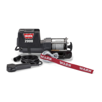
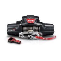
Winch
Top Plastic
Figure7
Figure8
Figure9