Do you have a question about the Warn P2500 and is the answer not in the manual?
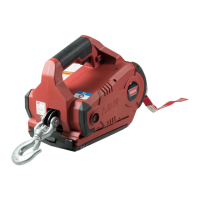
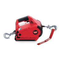
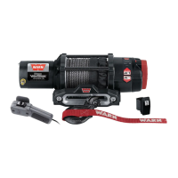
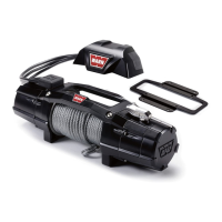
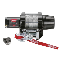
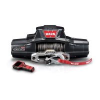
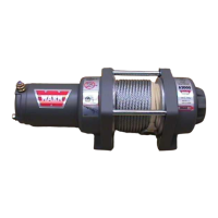
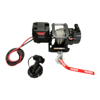
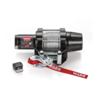
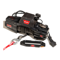
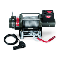
Guides users in correctly identifying the winch model and part number for accurate repair and parts ordering.
Defines major structural components and explains the operational principles of Warn planetary winches.
Highlights that the manual is intended for authorized service technicians and stresses proper tools and adherence to instructions.
Lists the necessary tools recommended for performing disassembly and reassembly procedures on the winch.
Provides step-by-step instructions and safety warnings for taking apart and putting back together the winch components.
Details the process of removing the winch motor, emphasizing noting wire placement and securing the wire rope.
Explains how to remove the armature from the motor, including checks for wear and damage to the commutator.
Guides on correctly inserting the armature into the motor casing and inspecting the housing for damage.
Outlines the steps for reinstalling the motor, noting the need to remove the drum support plate and check for specific parts.
Details the procedure for replacing the motor cap assembly, emphasizing alignment of index marks and proper bolt tightening.
Describes reassembling the motor housing, including replacing gears, thrust washers, and cable protectors correctly.
Provides instructions for disassembling the clutch housing, including noting motor placement and securing the wire rope.
Guides on reassembling the clutch housing, including greasing parts, replacing gears, and aligning components.
Lists the necessary tools for brake removal and replacement procedures, including retaining ring pliers and a screwdriver.
Details the steps for disassembling the winch brake assembly, including removing retaining rings and gears.
Provides instructions for reassembling the brake, including cleaning, greasing, and replacing components correctly.
Explains the different types of winch control operations including dial, contactor, and solenoid controls.
Details the wiring and operation of the dial control switch, including its connection to the battery and winch through a solenoid.
Describes the electrical operation of the contactor control pack, including power to the remote socket and wire triggers for different modes.
Explains the wiring of solenoid control packs, emphasizing the use of diodes for safety and operation in power-in and power-out modes.
Details the components and wiring of the pull pack solenoid control pack, including solenoids, a diode, and electrical cables.
Addresses issues where the winch fails to hold its load, listing possible causes like incorrect rope spooling or exceeding load ratings.
Troubleshoots overheating brakes and loss of holding power, suggesting causes like incorrect spooling or prolonged power-out cycles.
Helps diagnose problems with manually spooling wire rope, citing bent drum flanges or worn drum bushings as potential causes.
Covers common power issues, including grounding problems, loose connections, battery faults, armature wear, and solenoid failures.
Addresses diminished pulling power, suggesting causes like damaged remote controls, incorrect ground connections, or worn clutch housing.
Diagnoses issues where only a clicking sound is heard, pointing to faulty grounding, battery problems, water damage, or sticking solenoids.
Explains causes of electrical sparks, such as improper motor installation, water ingress, or worn brushes due to armature issues.
Troubleshoots winches operating in only one direction, attributing it to damaged remote controls, loose pins, or sticking solenoids.
Addresses dial switch malfunctions, suggesting causes like bent switch bases or incorrect wiring.
Identifies issues where the switch is burned, likely due to incorrect wiring or improper installation.
Diagnoses melted wire harness insulation, caused by the switch being held in the 'on' position during stalling or poor installation.
Covers wire rope issues where it gets behind the drum flange, potentially damaging bushings or the rope itself.