Do you have a question about the Warn 84705 and is the answer not in the manual?
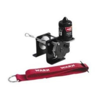
Locate and position the contactor on the right rear inner fender, near the rear tool box, securing with bolts.
Mount the winch switch on the left handlebars, connect wires to ignition harness and route to contactor.
Connect electrical cables to contactor and winch motor, route battery cables to battery, secure all wiring.
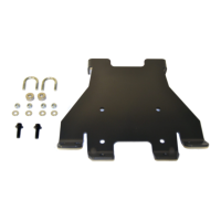
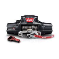
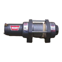
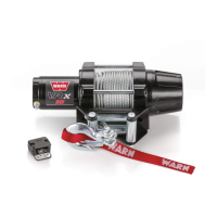
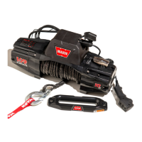
This document provides installation instructions for the WARN Winch Mounting Kit, part number 84705, designed for Honda Foreman 500 and Honda Rubicon ATVs. The kit facilitates the integration of a WARN ATV winch (sold separately) onto the vehicle, enabling recovery and utility functions.
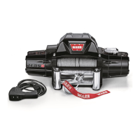
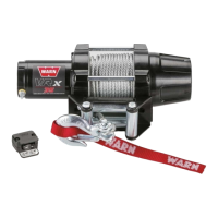
The WARN Winch Mounting Kit serves as a robust interface between a WARN ATV winch and the front frame of specific Honda ATV models. Its primary function is to securely attach the winch and its associated components, such as the roller fairlead, to the vehicle. This allows the winch to be used for various tasks, including vehicle recovery, pulling, and other utility applications. The installation process involves removing several front-end components of the ATV, installing the mounting plate and winch, and then reassembling the vehicle's front end. The kit also includes specific wiring instructions tailored to the Honda Foreman 500 and Rubicon, ensuring proper electrical connection and operation of the winch.
The kit itself is a mounting solution, and its technical specifications primarily relate to the fasteners and torque values required for installation.
The kit itself is not a functional device but enables the use of a WARN ATV winch. Key usage features facilitated by the kit include:
The document emphasizes the importance of regular maintenance for the winch, winch mount, and related hardware to ensure safety and longevity.
The installation process is comprehensive, starting with the removal of various front-end components like the skid plate, plastic fascia, and bumper. The mounting plate and winch are then installed, followed by the reassembly of the vehicle's components. Special attention is given to the electrical wiring, with detailed steps for locating the contactor, installing the handlebar switch, and routing all electrical cables to avoid potential hazards. The document stresses the importance of safety throughout the installation and operation, with clear warnings about potential injury and equipment damage if instructions are not followed.