WARN INDUSTRIES PAGE 15 84856A0
Please refer to gure 15 for the wiring schematic
Notice
The winch is now fully operable. Test to conrm
operation in all modes. Proceed to section VI, en-
titled “Maintenance/Care”.
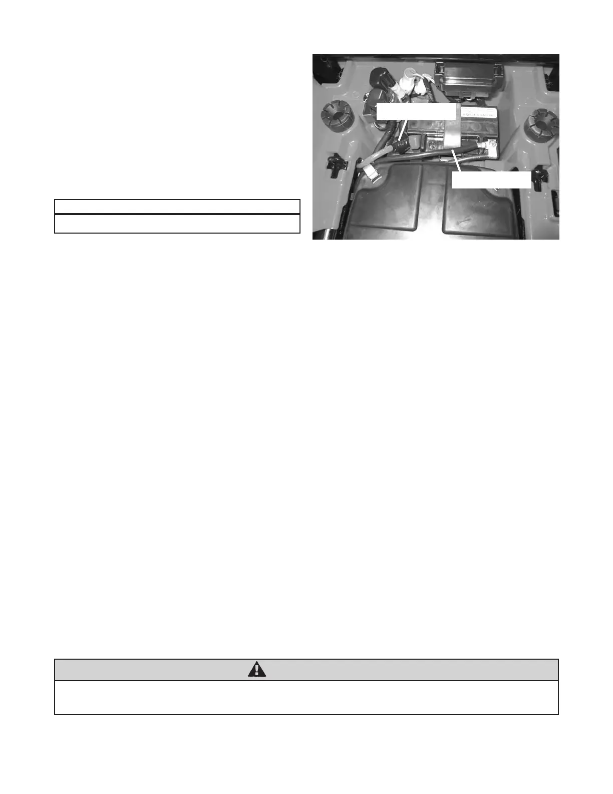
c. Attach the red wire to the red contactor post and
battery positive terminal, gure 30. Attach the black
wire to the black contactor post and battery negative
terminal, gure 30. Reposition the protective boot
over the positive battery terminal.
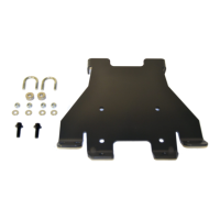
d. Reinstall the side panels that were removed in
Section 5, Step 2d. Use the original hardware to
reattach the side panel.
d. Reinstall the seat.
VI. Maintenance/Care
• Inspect all metal parts on the winch, winch mount, and related hardware. Replace all that appears rusted,
cracked or deformed prior to use.
• Inspect all nuts and bolts on the winch, winch mount, and related hardware prior to each use. Tighten all nuts
and bolts that are loose. Missing, stripped, fractured, or bent bolts or nuts need to be replaced immediately.
• Check all cables prior to use. Replace cables that are worn or frayed.
• Check all moving and rotating parts. Remove debris that may inhibit the part from moving freely.
WARNING
Failure to perform regular inspections and maintenance on the winch, winch mount, and related hard-
ware may result in vehicle damage and operator injury or death.
Figure30BatteryCover
BlackBatteryCable
RedBatteryCable