WARN INDUSTRIES PAGE 13 84856A0
WARNING
Avoid all moving and potentially hot components
of ATV when routing electrical cables. Avoid
areas where the wiring could be pinched when
components are reinstalled. Failure to do so can
result in product failure which can lead to vehicle
damage and operator injury or death.
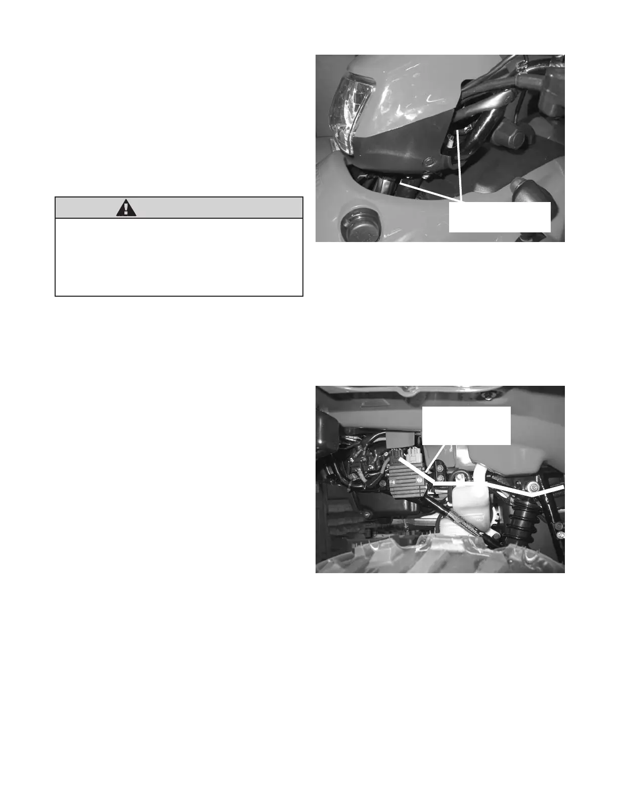
e. Route the switch leads down the steering column,
gure 25, to the rear of the ATV. Route switch
leads in such a manner to follow other original wire
harnesses along the right side of the frame to the
contactor, gure 25, gure 26 and gure 27. Utilize
existing plastic tie straps to secure handlebar switch
wire.
f. Reinstall the handlebar cowl. Use the original
hardware to reattach the handlebar cowl. Tighten
the bolts securely.
3. Wiring Installation - Step Six in the Installation
and Specication Guide:
a. Connect the yellow and blue electrical cables to
the contactor, gure 15, gure 19, gure 20 and
gure 26. Route the winch wires (yellow and blue)
from the contactor to the front of the ATV, gure
28. The routing should follow along the right side
frame tube to the front of the ATV, gure 26, gure
27 and gure 28. Place the motor terminal boots,
supplied in the mounting kit, onto the electrical
cables. Attach the yellow and blue 6 Ga wires to the
motor terminals on the winch, gure 28. Yellow is
marked #1 and blue is marked #2 on the end of the
motor cap. Slide the motor terminal boots over the
motor terminals. The electrical cables route above
the front differential and along the inside of the left
front frame down-tube. Use cable ties to secure all
electrical cables to the ATV frame. Avoid all moving
and potentially hot components of the ATV when
routing the electrical cables.
Note: Itmaybenecessarytoremoveorloosenthe
frontplasticfasciatogainenoughaccessto
themotorterminal.
RouteSwitchWires
downSteeringColumn
Figure25RouteSwitchWires
Figure26RoutingElectricalCables
RouteCablesAlong
FrameTubeand
ExistingWireHarness