WARN INDUSTRIES PAGE 12 84856A0
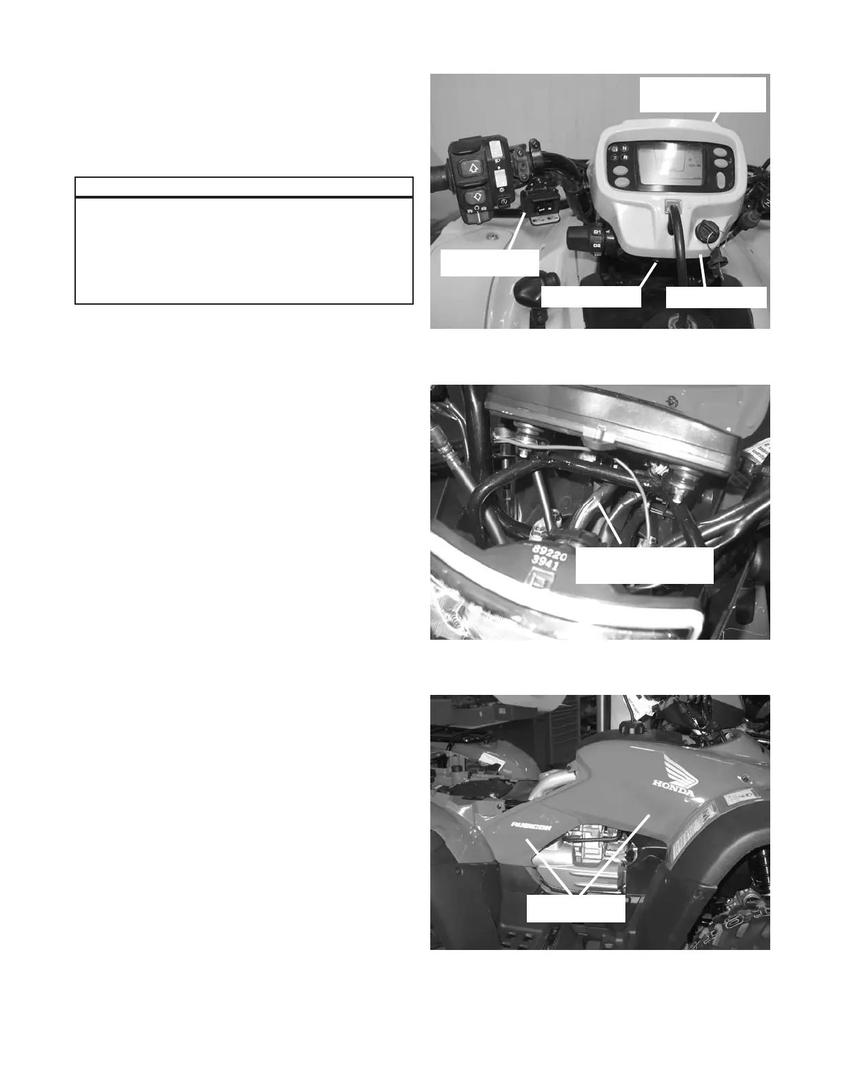
b. Mount the winch switch in the location shown in
gure 22. The recommended location is on the
bottom of the left side of the handlebars.
c. Remove the handlebar cowl, by removing the three
fasteners (two on the side, one in front) to expose
the ignition switch wire harness, gure 23. Cut back
the harness protective cover and splice the red
switch wire, using the scotch lock supplied in the
mounting kit, into the pink wire located in the ignition
switch wire harness. Before making the splice,
make sure that the pink wire only has power when
the key switch is on. Trim the red switch wire excess
approximately 20cm (8 in). Retape with electrical
tape.
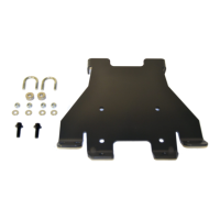
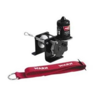
d. Remove the left and right side panels by removing
the fasteners holding them in place, gure 24. Keep
these fasteners for reinstallation.
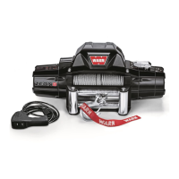
Please refer to the Installation and Specication
Guide, supplied in the winch kit, for specic
details on how to install the switch onto the ATV.
Please note that the switch extension brackets
are not used in the Rubicon and Foreman
application.
Notice
Figure23ConnectingSwitch-RedWire
IgnitionSwitchWire
Harness
Figure24RemoveSidePanels
RightSidePanels
Figure22SwitchLocation
SwitchLocation
HandlebarCowl
RouteSwitchWires
DownSteeringColumn
RemoveFastener