WARN INDUSTRIES PAGE 11 84856A0
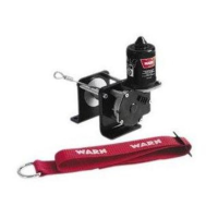
Figure21RedWire-Tie-off25cm(10in)
RedWire
Secureadistanceof25cm
(10in)fromthispoint
Securewith
ElectricalTape
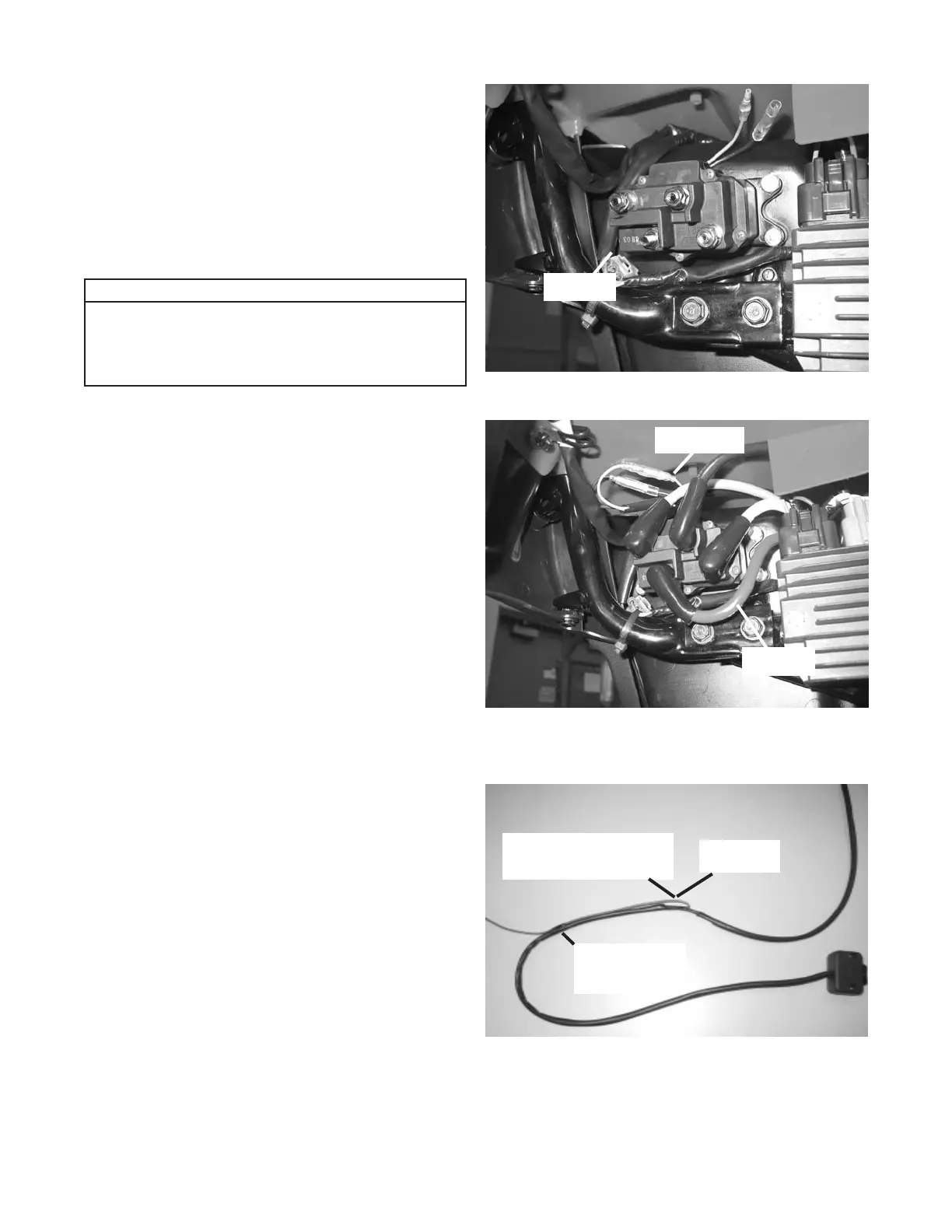
e. Position the contactor with the post for the positive
battery cable (red cable) in the lower left corner
(leads for the handlebar switch are positioned
up), gure 19 & 20. Mark and drill 1/4” holes for
contactor. Secure the contactor with four 1/4-20 x
1” bolts, washers, lock-washers and nuts supplied
with the winch. Tighten the nuts to a recommended
torque of 7 N-m (5 ft-lb).
2. Handlebar Switch Installation - Step Four in the
Installation and Specication Guide:
a. Before installing the winch switch, route the red wire
towards the switch case. Secure with electrical tape
a distance of approximately 25cm (10in) from where
the red wire protrudes from the back casing towards
the switch case, gure 21. This will allow you to see
the red wire when routing the switch wires, down the
steering column, to the contactor.
Notice
Please note that all wires in the wiring
photographs are shown without conduit on
the colored wires. This is for clarity in the
instructions.
Figure19ContactorLocation-RightSideofToolBox
RedCable
Figure20ContactorLocation-RightSideofToolBox
SwitchLeads
RedCable