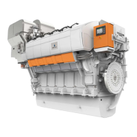
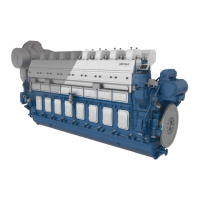
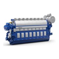
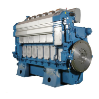
Do you have a question about the Wartsila 9L46F and is the answer not in the manual?
Details the maximum continuous power output of the Wärtsilä 46F engines.
Provides physical dimensions and weight specifications for in-line and V-engines.
Defines the acceptable operating parameters and speed limitations for the engine.
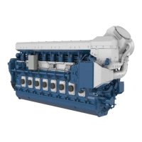
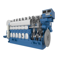
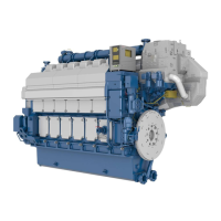
Describes the key mechanical components and systems of the Wärtsilä 46F engine.
Details the fuel injection system, including low-pressure fuel lines and twin plunger pumps.
Describes the engine's dry oil sump and standard lubricating oil system configuration.
Explains the division of the cooling water system into HT and LT circuits.
Details the SPEX turbocharging system and the two-stage charge air cooler.
Describes the Wärtsilä Unified Controls (UNIC) automation system and its modules.
Details factors to consider when selecting pipe dimensions, including material and velocity.
Explains how to determine piping pressure classes based on operating and design pressures.
Classifies piping systems based on DNV rules, considering media, pressure, and temperature.
Outlines procedures for cleaning and protecting piping systems before installation and service.
Gives guidelines for proper installation of flexible pipe connections to prevent damage from vibration.
Provides guidelines for fixing pipes to rigid structures near flexible connections to prevent vibration damage.
Details fuel specifications based on ISO 8217:2017, including additional properties.
Describes distillate fuel grades ISO-F-DMX, DMA, DMZ, and DMB.
Illustrates the internal fuel system for in-line and V-engines with component and pipe connection details.
Covers design considerations for external fuel systems, including cleaning, viscosity, and circulation.
Details fuel treatment processes, focusing on separation efficiency and separator operation.
Explains the importance of centrifugal separators for heavy fuel cleaning and their operation modes.
Illustrates the fuel feed system for MDF installations with component and pipe connection details.
Illustrates the fuel feed system for HFO installations with component and pipe connection details.
Describes the components included in a typical feeder/booster unit.
Provides instructions for flushing the external piping system before engine connection.
Details the specifications for engine lubricating oil, including viscosity and alkalinity.
Specifies SAE viscosity class, VI, and Base Number (BN) requirements for engine oil.
Illustrates the internal lubricating oil system for in-line and V-engines.
Details the external lubricating oil system for engine-driven and electrically driven pumps.
Explains the requirements for the lubricating oil separator unit for continuous separating.
Details the typical equipment included in lubricating oil separator units.
Details the recommended oil tank volume and installation considerations.
Details the lubricating oil pump type, design data, and required power examples.
Explains the mandatory use and operation of the pre-lubricating oil pump.
Details the design data for the external lubricating oil cooler.
Specifies the quality requirements for instrument air used in safety and control devices.
Describes the engine starting system using compressed air and associated components.
Covers design regulations for starting air systems, including receivers and compressors.
Details dimensioning and pressure requirements for starting air vessels.
Specifies pH, hardness, chloride, and sulphate limits for fresh cooling water.
States that the use of approved cooling water additives is mandatory.
Illustrates the internal cooling water system for in-line engines.
Details the external cooling water system, including components and pipe connections.
Details electrically driven pumps for HT and LT circulation, including stand-by pump requirements.
Provides design guidelines for the fresh water central cooler, including flow and pressure drop.
Details ventilation requirements, including air intake design, overpressure, and heat sources.
Explains how to design the combustion air system, including filter placement and fan selection.
Illustrates the charge air and exhaust gas system for in-line engines.
Covers design factors for external exhaust systems, including piping, support, and back pressure.
Covers exhaust gas silencing options, including Compact Silencer System (CSS) and conventional silencers.
Explains the main components of diesel engine exhaust emissions, including CO2, water, and secondary products.
Covers marine exhaust emission regulations, including IMO Tier 3 NOx standards.
Details the IMO's MARPOL Annex VI regulations on marine exhaust emissions.
Explains primary and secondary methods for reducing diesel engine exhaust emissions.
Describes the UNIC C2 system, its CAN-bus communication, and modules.
Explains the functions of the engine safety module for overspeed protection and shutdown.
Covers engine functions like starting, stop/shutdown, and speed control.
Details the procedures for normal and emergency engine stops and safety shutdowns.
Explains the electronic speed control for main engines and generating sets.
Provides guidelines for propulsion control and power management systems in diesel-electric ships.
Details resilient mounting using steel spring elements to reduce vibrations and noise.
Covers working space around the engine, engine room height, and maintenance platforms.
Provides detailed service space requirements for in-line engines.
Provides detailed service space requirements for V-engines.
