EasyManua.ls Logo

Waters nanoACQUITY UPLC User Manual

Waters nanoACQUITY UPLC
76 pages
To Next Page IconTo Next Page
Page #1 background imageLoading...
Page #1 background image
nanoACQUITY UPLC
System
Quick Start Guide
71500097503/Revision D
Copyright © Waters Corporation 2006.
All rights reserved.
CORPORATION

Table of Contents

Question and Answer IconNeed help?

Do you have a question about the Waters nanoACQUITY UPLC and is the answer not in the manual?

Waters nanoACQUITY UPLC Specifications

General IconGeneral
System TypeUltraPerformance Liquid Chromatography (UPLC)
Maximum Pressure15, 000 psi (1034 bar)
Power Requirements100-240 VAC, 50/60 Hz
Flow Rate Range0.1 to 2.0 mL/min
Column Temperature Range20 to 90 °C
Sample CapacityUp to 96-well plates or 2 mL vials
Detector CompatibilityUV/Vis, MS, ELSD, CAD
Gradient MixingBinary, quaternary
SoftwareEmpower Software
Injection Volume0.1 to 10 µL

Summary

Operating this device

Observing safety precautions

Using Waters equipment

Safety and electromagnetic equipment compatibility

United States – FCC rules

Device compliance with Part 15 of FCC Rules and potential interference causes.

United States – safety requirements

System meets OSHA safety requirements evaluated by NRTL.

Canada - spectrum management

Europe – safety and electromagnetic compatibility

Australia – emissions requirements

nanoACQUITY UPLC system information

Intended use

System is for analyzing compounds and introducing samples into a mass spectrometer.

Biological hazard

Handle physiological fluids with precautions; treat specimens as potentially infectious.

Calibration

Follow acceptable methods using pure standards to calibrate methods.

Quality control

Run three quality-control samples representing subnormal, normal, and above-normal levels.

1 System Overview

Instruments and components

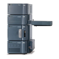
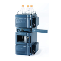
System designed for capillary-to-nano-scale separations, including solvent managers, sample manager, and detectors.

nanoACQUITY operating modes

nanoACQUITY binary solvent manager

Auxiliary solvent manager

Flow control module

Monitors solvent flow in the channel, calibrated for water, acetonitrile, and methanol.

Sample manager

Sample consumption guidelines

Guidelines for sample consumption based on system configuration and injection mode.

Heating and trapping module

TUV optical detector

Mass detectors

Q-Tof Premier™

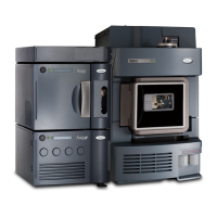
Exact-mass API/MALDI MS/MS platform for pharmaceutical and biotech industries.

LCT Premier™

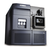
Benchtop mass spectrometer for high-resolution, time-of-flight measurements.

MassLynx data system

nanoACQUITY UPLC Console

2 Preparing System Hardware

Powering-on the system

Procedure for starting system modules, workstation, and software.

Monitoring startup tests

Monitoring the LEDs of system instruments

Power LED

LED on the front panel indicating if the module is powered on or off.

Status LEDs

LEDs indicating module state: idle, operating normally, or error.

Preparing the auxiliary solvent manager

Priming the seal wash

Lubricates plungers and flushes salts from the auxiliary solvent manager.

Priming the auxiliary solvent manager

Preparing the binary solvent manager

Priming the seal wash

Lubricates plungers and flushes salts from the binary solvent manager.

Priming the binary solvent manager

Preparing the sample manager

Selecting weak and strong wash solvents

Guidelines for selecting wash solvents for optimal performance.

Priming the sample manager

Washing the sample manager needle

Characterizing the needle seal

Characterizing the needle and sample loop volumes

Loading sample plates in the sample manager

Preparing the detector

Preparing the TUV detector

Steps for starting and verifying the TUV detector operation.

Recording sample and reference energies

Preparing the mass spectrometer

Conditioning the column

Shutting down the system

Between analyses

Procedure for shutting down the system between analytical runs.

Overnight or weekends

Procedure for shutting down the system overnight or for a weekend.

More than 72 hours (long-term)

3 Configuring System Software

Configuring MassLynx

Steps to configure MassLynx software for instrument control.

Starting the nanoACQUITY UPLC Console from MassLynx

Configuring events

4 Verifying System Operation

Required materials

List of materials needed for system verification testing.

Preparing the mobile phases

Preparing the sample

Preparing the system

Creating the test methods

Creating the instrument method

Steps to create instrument methods with binary solvent manager parameters.

Performing the test

Related product manuals