Do you have a question about the Watlow 942 Series and is the answer not in the manual?
Provides an overview of the Series 942, its features, and capabilities.
Instructions on how to remove the control chassis from its case.
Explains the function and location of DIP switches for configuration.
Guidance on planning the installation and wiring of the Series 942.
Details on mounting dimensions and physical installation of the unit.
Step-by-step instructions for physically installing the unit in a panel.
Wiring diagrams and instructions for connecting power to the Series 942.
Recommendations for optimal sensor placement and mounting.
Details on wiring different input types like Thermocouple and RTD.
Instructions for wiring 0-5VDC and 4-20mA process inputs.
Wiring for Solid State Relay and Switched DC outputs for Output 1.
Wiring for Mechanical Relay and Process 0-10VDC outputs for Output 1.
Wiring for Process 4-20mA and 0-20mA outputs for Output 1.
Wiring for Process 0-5VDC and Solid State Relay outputs for Output 1.
Wiring for Solid State Relay and Switched DC outputs for Output 2.
Wiring for Mechanical Relay and Solid State Relay outputs for Output 2.
Wiring for Mechanical Relay outputs for Auxiliary Option 1 and 2.
Wiring for Mechanical Relay outputs for Auxiliary Options 3 and 4.
Wiring for Retransmit outputs for Auxiliary Options 5 and 6.
Illustrates a typical system wiring configuration with components.
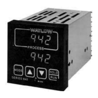
Identifies front panel keys and their functions, and display elements.
Instructions on how to access the device's setup configuration menu.
Details the various parameters available for configuration in the setup menu.
Explains parameters like Output 1, Hysteresis 1, Output 2, and Hysteresis 2.
Covers parameters for Output 4, Alarm 2, Latching, Hysteresis 4, RTD, and Program Type.
Details parameters for Profile Start, Baud rate, Data bits, Protocol, Address, Log, Interval, and Tag.
A table summarizing setup parameters, their values, ranges, and defaults.
Defines parameters for setting the operating set point and program selection.
Details parameters like Proportional Band, Reset/Integral, Rate/Derivative, Cycle Time, and Dead Band.
Covers Alarm parameters (Low, High), Calibration Offset, and Auto-Tune.
Introduces the Program menu for creating and managing profiles.
Describes parameters for Set Point, Hour, Minute, Second, Rate, and Events.
Details parameters for Soak, Jumploop, and End steps in programming.
Instructions on how to start and run a programmed profile.
Instructions on how to resume a previously halted program profile.
Explains the capability of two event outputs for controlling peripheral devices.
Explains the gSd feature for maintaining temperature within a set window.
Describes how to create multiple profiles by chaining steps.
Describes the jumploop feature for backward jumps in profile steps.
Guides through creating a basic ramp and soak profile.
Instructions on how to start and run a programmed profile.
Steps to modify an existing programmed profile and its parameters.
Guide to using the auto-tuning feature for PID parameter adjustment.
Detailed steps for manually tuning PID parameters for optimal control.
Instructions for changing the position of auxiliary jumpers.
Explains how to set up and use Process and Deviation alarms.
Provides an example illustrating how deviation alarms function.
Shows how alarms are displayed on the unit's screen.
Lists and defines various error codes and their causes.
Explains how to clear errors and the resulting behavior of the unit.
Lists the various control modes and features supported by the Series 942.
Describes the physical interface, displays, and keys of the control unit.
Details the specifications for secondary output types.
Specifies the types and capabilities of auxiliary outputs.
Describes the specifications for retransmit output options.
Details the accuracy specifications for the device.
Lists communication standards and protocols supported by the unit.
Lists certifications and approvals obtained for the product.
Describes the type of screw terminals used for connections.
Specifies power requirements and capabilities.
Defines the recommended environmental conditions for operation.
Provides physical dimensions of the control unit.
Identifies the main control unit and its basic configuration.
Lists the available input sensor types the unit can accept.
Details the various types of primary outputs available for the unit.
Lists the available types for the secondary output.
Describes the available options for auxiliary outputs.
Specifies the communication interface options.
Recommendations for positioning and routing wires to minimize noise.
Identifies common sources of noise interference in wiring.
Provides a reference for further wiring guidelines from IEEE.
Details methods for reducing noise sensitivity through wire routing and grounding.
Describes the use of snubbers, MOVs, and line filters to reduce noise.
Provides a method to test for and identify ground loops in the system.
Lists Watlow noise suppression components and their part numbers.
Shows different filter wiring configurations for noise removal.
Steps to access the control's calibration menu.
Lists the parameters and procedures for calibrating various inputs/outputs.
Step-by-step instructions for calibrating thermocouple inputs.
Lists the necessary equipment for thermocouple calibration.
Step-by-step instructions for calibrating RTD inputs.
Lists the required equipment for RTD calibration.
Step-by-step instructions for calibrating 0-5V inputs.
Lists the necessary equipment for 0-5V input calibration.
Step-by-step instructions for calibrating 4-20mA inputs.
Lists the necessary equipment for 4-20mA input calibration.
Step-by-step instructions for calibrating 0-5/0-10V outputs.
Lists the necessary equipment for 0-5/0-10V output calibration.
Step-by-step instructions for calibrating 0-20/4-20mA outputs.
Lists the necessary equipment for 0-20/4-20mA output calibration.
Step-by-step instructions for calibrating 0-5V retransmit.
Lists the necessary equipment for 0-5V retransmit calibration.
Step-by-step instructions for calibrating 4-20mA retransmit.
Lists the necessary equipment for 4-20mA retransmit calibration.
| Brand | Watlow |
|---|---|
| Model | 942 Series |
| Category | Data Loggers |
| Language | English |