Do you have a question about the Watson Marlow Pumps 101F and is the answer not in the manual?
Pump unit complies with Machinery Directive 2006/42/EC, EMC Directive 2004/108/EC when used standalone.
When integrated with other machinery, the relevant machinery must be declared compliant with Machinery Directive 2006/42/EC.
Caution regarding dangerous voltages inside the pump; isolate from mains before removing the cover.
Covers repair or replacement of parts failing within two years due to material or workmanship defects.
Procedure for returning pumps, requiring decontamination and a certificate for hazardous substances.
Guidelines for short lines, correct bore, viscous fluids, tube length, and cleanliness.
Guidance on selecting compatible tubing materials based on chemical compatibility lists.
Instructions for positioning the pump, setting voltage selector, and wire colour coding for mains connection.
Checks to perform if the pump fails to operate, focusing on power, supply, and fuse.
Simple instructions for starting and stopping the 101F/R pump using the power switch.
Controls for manual operation, including direction change, speed setting, and priming.
Setting the Auto/Manual switch for remote control via a 15-pin D connector.
Controlling pump flow rate via analogue signals (30V or 32mA), defining offset and range.
Details on input impedance, pin assignments, and polarity for voltage and current control signals.
Steps for setting signal offset and range potentiometers for accurate pump speed control.
Configuring panel switch, remote switch, or TTL signal for manual/auto mode selection.
Wiring for remote stop/start control using pins 8 and 13, including TTL input.
Signal availability at the Din socket, proportional to motor speed, with pin assignments.
Wiring a remote potentiometer for speed control, requiring calibration with offset and range settings.
Connecting a remote switch for direction control and disabling front panel reversing.
Guidance on cleaning the pumphead and case with detergent and water; no scheduled maintenance required for 101U/R.
Technical data including nominal rotor speed, voltage, power consumption, fuse rating, and operating ranges.
Technical data including maximum rotor speed, voltage, control ratio, power, fuse rating, and operating ranges.
Description of the twin roller pumphead, limited to silicone tubing use.
Details on flow rates for 101F/R and 101U/R using specific tubing, emphasizing application-specific determination.
Step-by-step guide for loading tubing into the pumphead, ensuring correct fit and rotation.
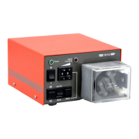
Diagram and list of spare parts for the 101U/R drive, including switches, LEDs, motors, and connectors.
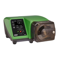
Diagram and list of spare parts for the 101F/R drive, including switches, motors, and fuses.
Detailed dimensional drawings of the 101U/R pump unit with key measurements provided.
Detailed dimensional drawings of the 101F/R pump unit with key measurements provided.
Table showing flow rates (ml/min) for the 102R pumphead based on tube number, bore, rpm, and pressure.
List of product codes for the 102R pumphead, categorized by tube size and material (Peroxide/Platinum Silicone).
Graphical representation of flow rates for the 102R pumphead against pressure and speed.
Warning that products are not designed for patient-connected applications.
Statement regarding information accuracy, liability, and the right to alter specifications without notice.
Form to declare substances in contact with returned products, for compliance with UK Health & Safety regulations.
| Brand | Watson Marlow Pumps |
|---|---|
| Model | 101F |
| Category | Water Pump |
| Language | English |