
B
Brandon MillerAug 21, 2025
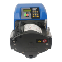
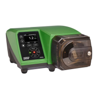
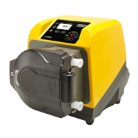
What to do if Watson Marlow Pumps Water Pump runs but there is little or no flow?
- HhlawsonAug 21, 2025
If your Watson Marlow Pumps Water Pump runs but produces little to no flow, consider the following: * Ensure fluid is adequately supplied to the pump. * Inspect the lines for any kinks or blockages. * Verify that all valves in the line are open. * Confirm the tube and rotor are correctly placed in the pumphead. * Check the tube for splits or bursts. * Make sure the correct wall-thickness tube is being used. * Verify the direction of rotation is correct. * Check that the rotor isn't slipping on the drive shaft.