14
Visit our website at http://watt-age.globalhobby.com or for Customer Service at http://globalservices.globalhobby.com
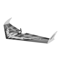
❑ Carefully install the two servos into the wing using
double-sided foam tape. When positioned properly, the
servos should be centered within the molded servo bays and
the servo horns should be toward the trailing edge of the
wing, as shown.
✦✦
✦✦
✦
IMPORTANT
✦✦
✦✦
✦ Before continuing, we strongly suggest temporarily installing the propeller and double-checking that
the propeller doesn't touch the ends of the ailerons. There should be an approximately 3/16" wide gap between the tips
of the propeller and the tip of the ailerons.
If you're using a different power system with a larger propeller, you will have to cut the ailerons shorter so they don't touch
the propeller. Make sure to do this before installing the control horns, clevises and pushrods.
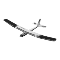
❑ Using a modeling knife, cut a small slot through one
aileron and install one control horn, making sure that the
control horn is 5/16" out from the end of the aileron (at the
hinge line) and that it is angled slightly toward the servo horn.
✦✦
✦✦
✦
IMPORTANT
✦✦
✦✦
✦
When installing the control horn, make
sure that the flat portion of the control horn backplate faces
away from the aileron, and make sure to push the backplate
until you hear it "click" firmly into place.
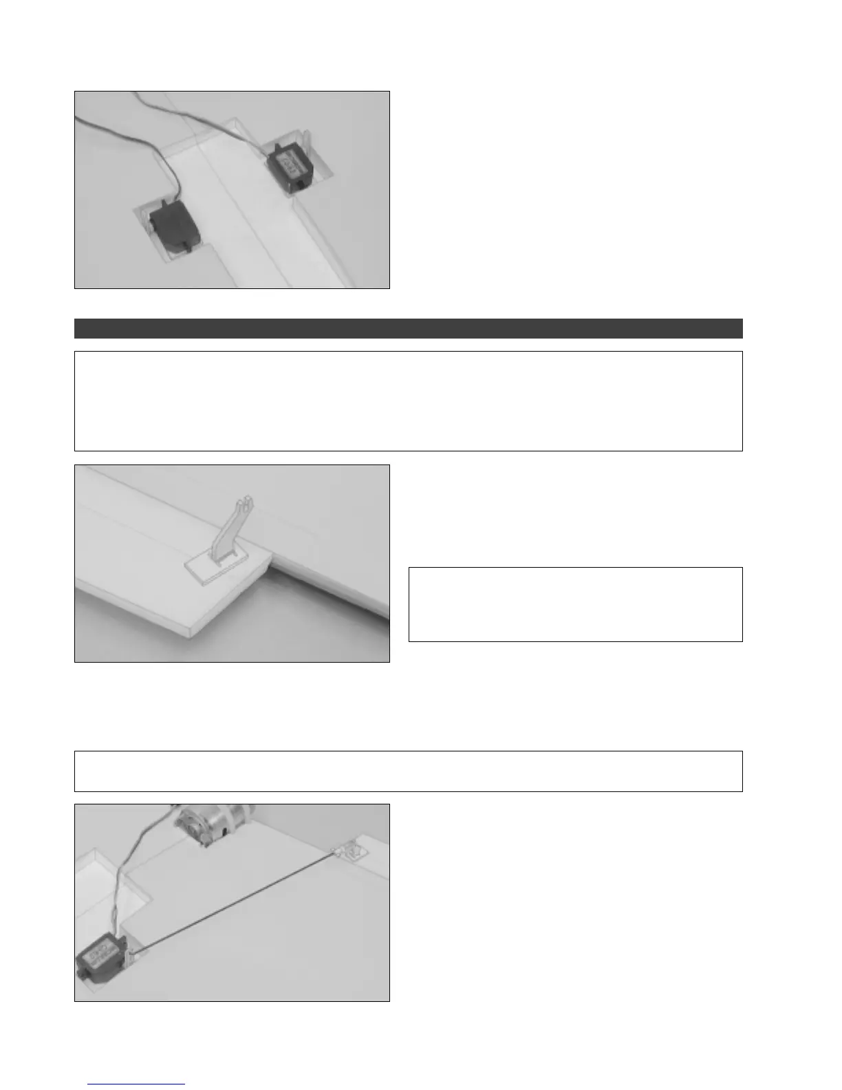
❑ Thread one nylon clevis onto one M1.5 x 150mm threaded wire and carefully snap the clevis into the control horn.
❑ With both the servo horn and the aileron centered, use a pencil to draw a mark on the pushrod wire where it crosses
the outermost hole in the servo horn.
✦✦
✦✦
✦
IMPORANT
✦✦
✦✦
✦
To center the aileron, hold a straight edge against the bottom of the wing. When the aileron is
centered, the bottom of the aileron should be flush with the straight edge.
❑ Remove the pushrod from the control horn and use
Z-Bend pliers to make a Z-Bend in the pushrod wire at the
mark you drew.
❑ Cut away the excess wire using a pair of wire cutters,
making sure to leave about 1/8" of wire beyond the Z-Bend.
❑ Install the pushrod wire into the outermost hole in the
servo arm, then snap the clevis into the control horn.
STEP 2: INSTALLING THE CONTROL HORNS, CLEVISES & PUSHRODS
 Loading...