INSTALLATION QUICK LOOK
Please follow 4 color tubing diagram to complete installation
CAUTION: When cutting supplied tubes, predeter-
mine the length by measuring the distance between
the components to be connected.
No tools are needed to connect 4 colored tubes.
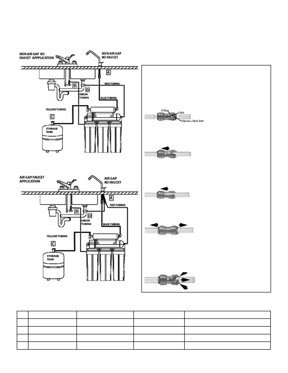
HOW TO MAKE A CONNECTION
1. CUT THE TUBE SQUARE
Cut the tube square. It is essential that the outside diameter
be free from score marks and that burrs and sharp edges be
removed before inserting into tting. For soft thin walled plastic
tubing we recommend the use of a tube insert.
2. INSERT TUBE
Fitting grips before it seals. Ensure tube is pushed into the tube
stop.
3. PUSH UP TO TUBE STOP
Push the tube into the tting, to the tube stop. The collet
(gripper) has stainless steel teeth which hold the tube rmly in
position while the o-ring provides a permanent leak proof seal.
4. PULL TO CHECK SECURE
Pull on the tube to check that it is secure. It is a good practice to
test the system prior to leaving site and/or before use.
Disconnecting PUSH COLLET AND REMOVE TUBE
To disconnect, ensure the system is depressurized before
removing the tube. Push in collet squarely against face of tting.
With the collet held in this position, the tube can be removed.
The tting can then be re-used.
Installation needs to comply with State and local plumbing regulations.
Connections Item No. Color of Tubing Description
A
RO Faucet FU-WDF-905-CP Blue Pure water to the Faucet
B
Feed Water Valve F560080 / F560070 Green Feed Water to RO System
C
Tank Ball Valve PSV501222W Yellow Pure Water to Storage Tank
D
Drain Connector SC500B14/38 Red Discharge Water to Drain
7