Benchmark Platinum-Edge: Operation-Service Manual
SECTION 3 - START SEQUENCE
OMM-0137_D • GF-211 • 7/16/2019 Technical Support • (800) 526-0288 • Mon-Fri, 8 am - 5 pm EST Page 18 of 146
Start Sequence
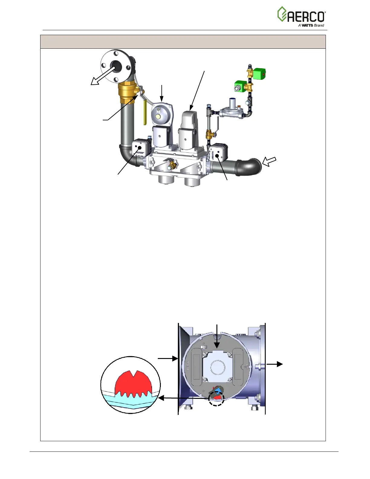
Figure 3-1e: BMK 5000-6000: SSOV Location
3. The Auxiliary Delay occurs for a configurable length of time and the Delayed Interlocks are
closed.
4. Once all required safety device switches are closed, a purge cycle is initiated and the
following events occur:
a. The Blower relay energizes and turns on the blower.
b. The Air/Fuel Valve rotates to the full-open purge position and closes purge position
switch. The dial on the Air/Fuel Valve (Figure 3-2a and 3-2b) will read 100 to indicate
that it is full-open (100%).
c. The Fire Rate bargraph on the Controller’s front face shows 100%.
Figure 3-2a: BMK 750 & 1000 Air/Fuel Valve in Purge Position
TO
BLOWER
AIR INLET
SSOV
VALVE
OFF VALVE
SSOV WITH
POC
PRESSURE SWITCH
- BMK 6000: 10.5” W.C., 2.6 kPa
- BMK 5000: 11.0” W.C., 2.7 kPa
PRESSURE SWITCH
- BMK 6000: 8.5” W.C., 2.1 kPa
- BMK 5000: 8.0” W.C., 2.0 kPa

 Loading...


