Benchmark Platinum-Edge: Operation-Service Manual
SECTION 7 – BOILER SEQUENCING TECHNOLOGY
OMM-0137_D • GF-211 • 7/16/2019 Technical Support • (800) 526-0288 • Mon-Fri, 8 am - 5 pm EST Page 91 of 146
7.3.5 Option 5 Remote Setpoint: Direct Wired Header Sensor & 4-
20ma Setpoint Drive
OPTION 5
Instructions: Remote Setpoint, Direct Wired Header Sensor, 4-20ma Setpoint Drive
NOTE:
Both Header Sensor and 4-20ma Direct Drive must be wired. See the Edge Controller
Manual (OMM-0139, GF-213) for more information.
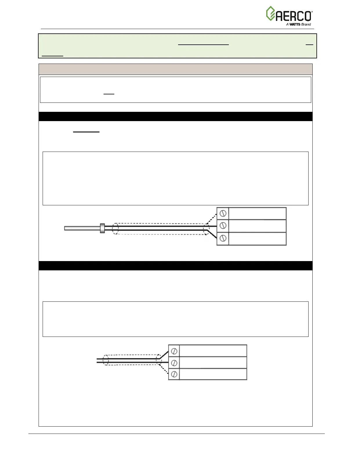
Step 1: HEADER SENSOR WIRING – MANAGER Unit
1. On the Manager unit, connect the Header Temperature Sensor (P/N 24410) to the I/O
board terminal strip J3, terminals 4 (Supply Header +) and 5 (Supply Header -).
2. Connect the shield to any Shield terminal, such as terminal 3 or 8 on strip J3.
NOTES:
• The header sensor must be installed between 2 and 10 feet (0.61 and 3.1m)
downstream of the LAST boiler in the plant’s supply water header.
• Shielded pair 18 - 22 AWG cable is recommended for header sensor wiring. There is no
polarity to be observed. The ground for the shield is at the Shield terminal on the I/O
the board. The sensor end of the shield must be left free and ungrounded.
Step 2: DIRECT WIRED 0-20mA or 4-20mA WIRING – MANAGER Unit
1. Connect the 4-20mA or 0-20mA terminals from the Direct Drive source to the I/O Board
strip J3, terminals 6 (Remote Analog In +) and 7 (Remote Analog In –) on the Manager.
2. Connect the shield to any Shield terminal on the I/O Board, such as terminal 3 or 8.
NOTES:
• Shielded pair 18 - 22 AWG cable is recommended for this connection. Polarity must be
observed.
• The ground for the shield is at the driver signal source.
Continued on next page
HEADER TEMP SENSOR
(P/N 24410)
Remote Signal +
Remote Signal –

 Loading...