Benchmark Platinum-Edge: Operation-Service Manual
SECTION 7 – BOILER SEQUENCING TECHNOLOGY
OMM-0137_D • GF-211 • 7/16/2019 Technical Support • (800) 526-0288 • Mon-Fri, 8 am - 5 pm EST Page 85 of 146
7.3.2 Option 2 Constant Setpoint: Modbus Wired Header Sensor
OPTION 2
Instructions: Constant Setpoint, Modbus Wired Header Sensor
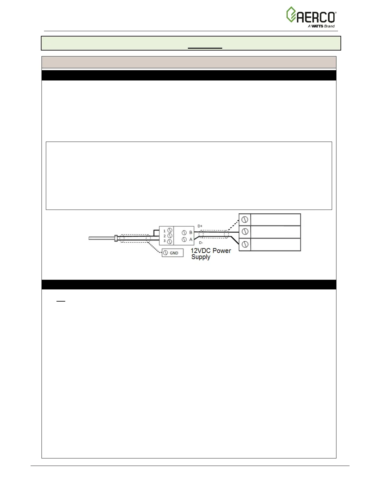
Step 1: MODBUS HEADER SENSOR WIRING – ANY BOILER
1. Connect the Modbus Transmitter (P/N 65169) terminal Pin B to the I/O Board strip J3,
terminal 13 (BST RS485+) and Pin A to terminal 15 (BST RS485–) on any of the Boiler
units using Shielded pair 18 - 22 AWG cable.
2. Connect the Header Temperature Sensor (P/N 24410) to pins 2 and 3 of the Modbus
Transmitter units using Shielded pair 18 - 22 AWG cable.
3. Install a jumper wire between pins 1 and 2 of the Modbus Transmitter.
NOTES:
• Polarity must be observed for the RS485 connections.
• Ground the shield to any Shield terminal on the I/O Board, such as Terminal 3 or 8.
• The Header Sensor must be installed between 2 and 10 feet (0.61 and 3.1m)
downstream of the LAST boiler in the plant’s supply water header.
• There is no polarity to be observed. The ground for the shield is at the power supply
ground. The sensor end of the shield must be left free and ungrounded.
Step 2: OPTION 2 CONFIGURATION
On All Boiler:
1. Go to: Main Menu Advanced Setup BST Cascade Cascade Configuration:
• Set the Unit Mode parameter to BST Client.
2. Go to: Main Menu
Advanced Setup BST Cascade Application Configuration:
• Set the Unit Address parameter to the communication address of the unit.
Continued on next page
HEADER TEMP SENSOR
(P/N 24410)

 Loading...