Benchmark Platinum-Edge: Operation-Service Manual
SECTION 4 – INITIAL START-UP
OMM-0137_D • GF-211 • 7/16/2019 Technical Support • (800) 526-0288 • Mon-Fri, 8 am - 5 pm EST Page 38 of 146
NATURAL GAS Manual Combustion Calibration Instructions
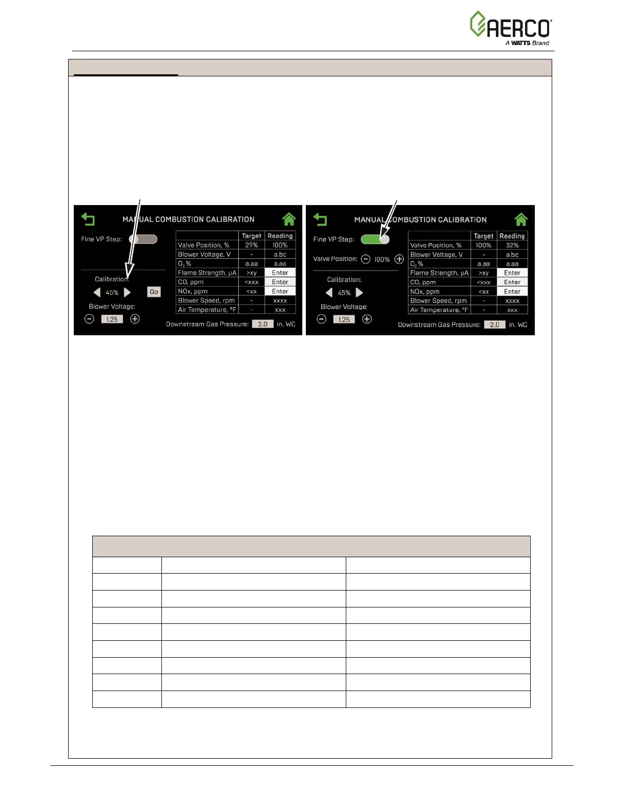
11. The main Manual Combustion Calibration screen appears. It provides two methods to
ramp the unit’s valve position up or down:
• Method 1: Toggle through the pre-set calibration points till you reach the desired
valve position, then press Go to go to that point (left image below).
• Method 2: Enable Fine VP Step, then manually press the + or – buttons once per
1% to bring the unit to the desired valve position (right image below).
PRESET CALIBRATION POINTS METHOD FINE VP STEP METHOD
Figure 4-6: Manual Combustion Calibration Screens
12. Set the Controller’s Enable/Disable switch to Enable.
13. Change the valve position to 30%, press the Go button, then verify that the unit has ignited
and is operating as expected.
14. Use the (Right) arrow key to change the valve position to 100%, then press Go.
15. Verify that the gas pressure on the downstream side of the SSOV is within the required
range shown in Table 4-1. If it isn’t, remove the brass hex nut on the SSOV actuator to
access the gas pressure adjustment screw (Figure 4-3). Make adjustments using a flat-tip
screwdriver, slowly rotating the gas pressure adjustment (in 1/4-turn increments)
clockwise to increase gas pressure or counterclockwise to reduce it. The resulting gas
pressure reading on the downstream manometer should fall in the range listed below.
TABLE 4-1: REFERENCE Gas Pressure Range @ 100% Fire Rate
2.0” ± 0.2” W.C. (0.50 ± 0.05 kPa)
2.4” ± 0.4” W.C. (0.60 ± 0.10 kPa)
BMK 1500 3.6” ± 0.1” W.C. (0.90 ± 0.02 kPa) 3.6” ± 0.1” W.C. (0.90 ± 0.02 kPa)
3.4” ± 0.2” W.C. (0.85 ± 0.05 kPa)
6.3” ± 0.1” W.C. (1.57 ± 0.02 kPa)
2.0” ± 0.1” W.C. (0.50 ± 0.02 kPa)
5.8” ± 0.1” W.C. (1.44 ± 0.02 kPa)
BMK 3000 2.1” ± 0.2” W.C. (0.52 ± 0.05 kPa) 6.0” ± 0.2” W.C. (1.49 ± 0.05 kPa)
6.3” ± 0.2” W.C. (1.56 ± 0.05 kPa)
6.3” ± 0.2” W.C. (1.56 ± 0.05 kPa)
7.9” ± 0.2” W.C. (1.97 ± 0.05 kPa)
7.9” ± 0.2” W.C. (1.97 ± 0.05 kPa)
16. With the valve position still at 100%, insert the combustion analyzer probe into the exhaust
manifold probe opening (see Figure 4-2a – 4-2c in Section 4.2.3) and allow enough time
for the combustion analyzer reading to stabilize.
PRE-SET CALIBRATION CONTROLS
FINE VALVE POSITION CONTROLS
 Loading...