STEP FOUR
TESTING THE WIRING
No wires should be connected to the control during the testing.
The following tests are to be performed using standard testing practices and procedures, and should only be carried out by properly
trained and experienced persons.
A good quality electrical test meter, capable of reading from at least 0 - 300 V (ac) and at least 0 - 2,000,000 Ohms, is essential to
properly test the wiring and sensors.
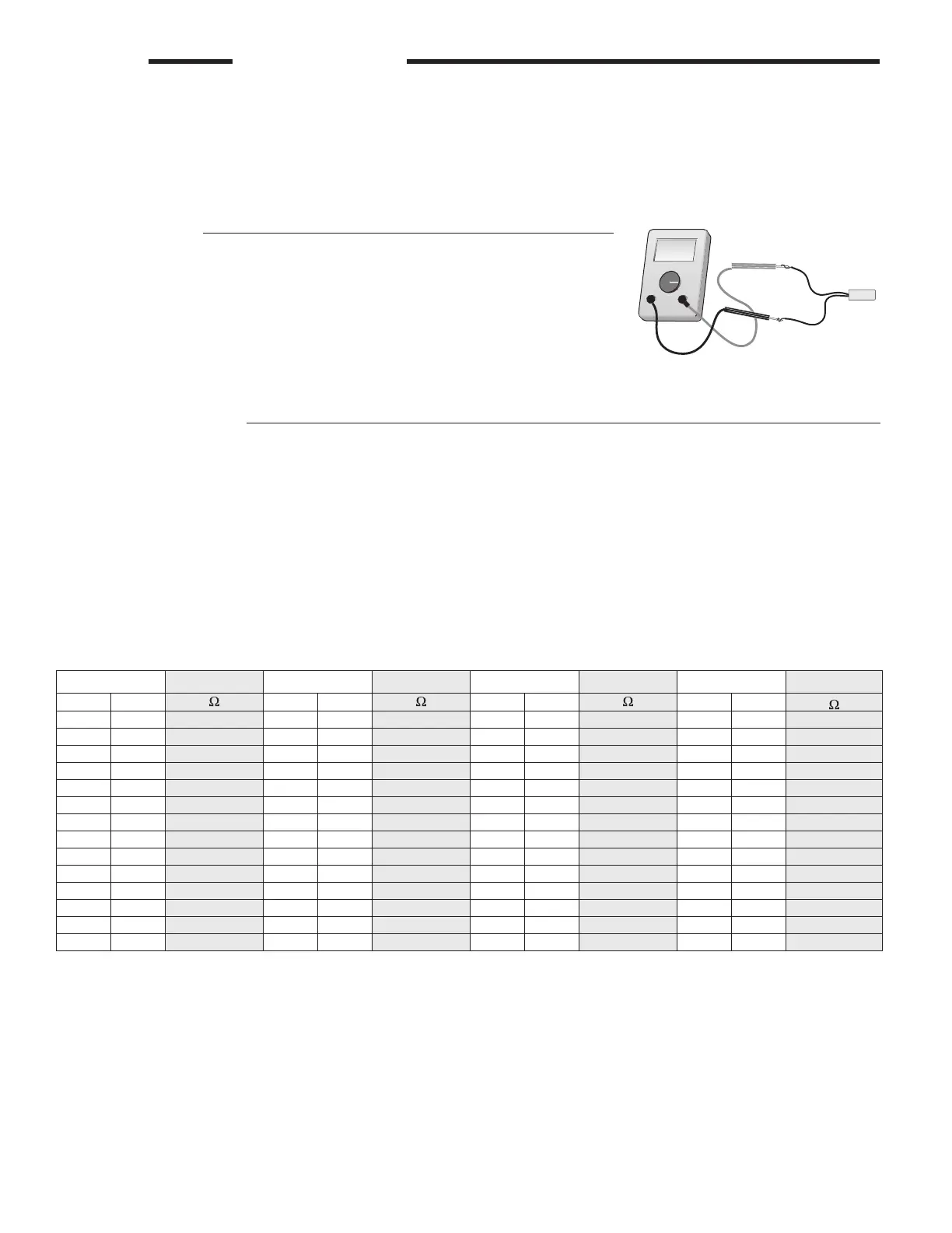
Test The Sensors
Ensure the sensor wires are not connected to the control terminals before testing. In order
to test the sensors, the actual temperature at each sensor location must be measured. A
good quality digital thermometer with a surface temperature probe is recommended for
ease of use and accuracy. Where a digital thermometer is not available, a spare sensor
can be strapped alongside the one to be tested, and the readings compared. Test the
sensors according to the following section.
Temperature Resistance Temperature Resistance Temperature Resistance Temperature Resistance
°F °C °F °C °F °C °F °C
-50 -46 490,813 20 -7 46,218 90 32 7,334 160 71 1,689
-45 -43 405,710 25 -4 39,913 95 35 6,532 165 74 1,538
-40 -40 336,606 30 -1 34,558 100 38 5,828 170 77 1,403
-35 -37 280,279 35 2 29,996 105 41 5,210 175 79 1,281
-30 -34 234,196 40 4 26,099 110 43 4,665 180 82 1,172
-25 -32 196,358 45 7 22,763 115 46 4,18 4 185 85 1,073
-20 -29 165,180 50 10 19,900 120 49 3,760 190 88 983
-15 -26 139,403 55 13 17,436 125 52 3,383 195 91 903
-10 -23 118,018 60 16 15,311 130 54 3,050 200 93 829
-5 -21 100,221 65 18 13,474 135 57 2,754 205 96 763
0 -18 85,362 70 21 11,883 140 60 2,490 210 99 703
5 -15 72,918 75 24 10,501 145 63 2,255 215 102 648
10 -12 62,465 80 27 9,299 150 66 2,045 220 104 598
15 -9 53,658 85 29 8,250 155 68 1,857 225 107 553
A good quality test meter capable of measuring up to 5,000 kΩ (1 kΩ = 1000 Ω) is required to measure the sensor resistance. In
addition to this, the actual temperature must be measured with either a good quality digital thermometer, or if a thermometer is not
available, a second sensor can be placed alongside the one to be tested and the readings compared.
First measure the temperature using the thermometer and then measure the resistance of the sensor at the control. The wires
from the sensor must not be connected to the control while the test is performed. Using the chart below, estimate the temperature
measured by the sensor. The sensor and thermometer readings should be close. If the test meter reads a very high resistance,
there may be a broken wire, a poor wiring connection or a defective sensor. If the resistance is very low, the wiring may be shorted,
there may be moisture in the sensor or the sensor may be defective. To test for a defective sensor, measure the resistance directly
at the sensor location.
Do not apply voltage to a sensor at any time as damage to the sensor may result.
Test The Sensor Wiring
Ω
Ω
V
Ω
12 of 20
© 2019 tekmar 256
_
D - 09/19
 Loading...