3,
Using
a comparator,
set
the
positive peak
to the
center
of the
scope.
Switch
the comparator
to
the negative
peak and
adjust R121 so that the
negative
peak equals the positive
peak.
Triangle
Amplitude
1. Set frequency
dial
for
2.0
(XI
K
range)
and
function
selector
to
•
2. Connect
oscilloscope,
with
peak
mV plug-in,
to
tab of switch
SW3B, as
illustrated under
“Square
Wave
Amplitude
Symmetry."
3. Adjust R56
on main board for positive peak
at
' -i
or . .-
1 4. -
-f-rr \ r t , „ .. .
t
, . *
.
i_
t
•
«
V
\J
I LD
—%J
|||V
\3CC
onciu
t
/
.
4. Adjust
R59
for
negative peak
at
—1
.25
V
±5
mV.
Negative Peak
Positive Peak
Output Amplifier
y/
1. Connect
oscilloscope to 50^2
OUT connector
with
50^2 terminator loaded at oscilloscope
(
1
j_j
function).
2.
Set FREQ HZ selector for
X1K
(FREQ
VER-
NIER
fully
cw)
and frequency
dial at 2.0.
3. Turn
OUTPUT
VERNIER (dB) fully
ccw.
4. Adjust
R150
for
amplitude symmetry
about
ground.
5. Set FREQ
HZ selector for XI
M
(2.0
dial
setting).
6. Turn
OUTPUT
VERNIER
(dB) fully cw.
7. Adjust
C64 to
provide
a
flat
square wave with
100
nanosecond
rise
time.
First
VCG
Null
y/
1. Connect
oscilloscope to 50&2
OUT
connector.
2. Set FREQ
HZ
selector to XI
K. Set
frequency
dial to
0.02
and turn FREQ VERNIER to CAL
position.
3. Short and
open
VCG IN to signal ground (out-
side of
BNC
connector) while monitoring out-
put frequency variation. Adjust
R11
for
mini-
mum
frequency
change using X20 horizontal
magnification on oscilloscope.
Time
Symmetry
y/
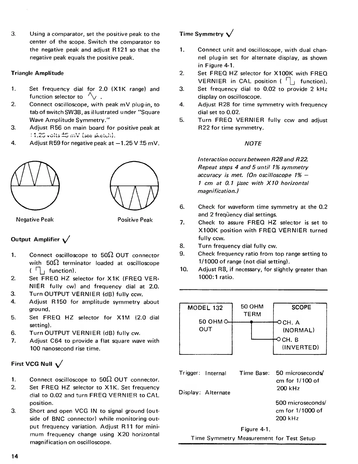
1. Connect unit and
oscilloscope, with
dual chan-
nel plug-in set for alternate
display,
as shown
in Figure
4-1
.
2. Set FREQ HZ selector for X100K
with
FREQ
VERNIER in CAL position
(
r
|_j
function).
3. Set frequency dial to 0.02
to provide
2
kHz
display on
oscilloscope.
4. Adjust R28
for
time symmetry with
frequency
dial set to 0.02.
5. Turn FREQ VERNIER
fully
ccw and
adjust
R22
for
time
symmetry.
NOTE
Interaction occurs between R
28 and R22.
Repeat
steps 4 and 5
until
1% symmetry
accuracy is met. (On oscilloscope
1%
—
1
cm at
0.1
(isec with X
10
horizontal
magni
fication.
)
6. Check
for
waveform time symmetry
at
the
0.2
and 2 frequency
dial settings.
7.
Check to assure
FREQ
HZ selector
is set to
X100K position with
FREQ
VERNIER
turned
fully ccw.
8. Turn
frequency
dial
fully cw.
9. Check frequency
ratio
from top range
setting to
1/1000 of
range
(not dial setting).
10.
Adjust R8, if necessary, for slightly
greater than
1000:1
ratio.
MODEL
132
50
OHM
SCOPE
TERM
50
OHM O—
—
i
6
o
X >
OUT
(NORMAL)
-OCH.
B
(INVERTED)
Trigger:
Internal
Time Base:
Display:
Alternate
50
microseconds/
cm
for
1/100
of
200
kHz
500
microseconds/
cm
for
1/1000
of
200
kHz
Figure
4-1
.
Time
Symmetry Measurement
for
Test Setup
14