Digital
Noise
Amplitude
Symmetry
\/
1. Set function selector
to
_JU
[_,
NOISE FREQ HZ
selector
to
160
kHz, and depress
SEQUENCE
LENGTH
-
215
-
1
push button.
2.
Connect oscilloscope, with peak mV
plug-in, to
location DN on
digital
board.
3.
Adjust R36, using comparator,
to provide
a
positive peak
of +1.25 V ±10 mV.
4. Adjust
R39, using comparator, to provide
a
negative
peak of
—1.25
V
±10
mV.
Analog Noise
Amplitude Symmetry
1. Connect BNC
cable to NOISE SYNC connector
(rear
panel) and sync
connector on oscilloscope.
2.
Depress
SEQUENCE LENGTH
-
2
1S
-
1
push
button.
3. Connect
oscilloscope
to
location AN on digital
board.
4. Adjust
R22 (gain) and R23 (balance)
to provide
a 2.5 V
p-p
signal centered
about ground.
S/N
Frequency
Compensation
\/
1. Set function
selector to
Hj
.
2.
Depress MODE
—
S/N push button.
3. Set frequency dial
to 1.0
and
FREQ HZ
selector
to X100K (100 kHz).
4. Set S/N
—
N/S
(dB)
selector to
+50 position
and turn vernier
to
+9
position to provide
ap-
proximately
+59 dB.
5. Turn
OUTPUT
VERNIER
(dB) full
cw.
6.
Connect
oscilloscope
to
50^2
OUT connector
with
5012 terminator
(
n
u
function).
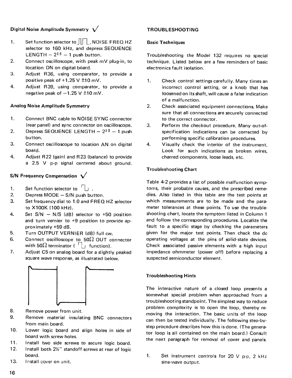
7.
Adjust
C5
on analog
board for
a
slightly
peaked
square
wave response,
as illustrated
below.
8.
Remove
power from
unit.
9.
Remove
material insulating
BNC
connectors
from
main
board.
10.
Lower
logic board and
align
holes in
side of
board
with screw holes.
11.
Install
two side
screws to secure
logic
board.
12.
Install
both
2y2
”
standoff
screws
at rear of logic
board.
13. I nstall
cover on unit.
TROUBLESHOOTING
Basic Techniques
Troubleshooting
the
Model
132 requires
no
special
technique.
Listed
below are
a
few
reminders
of
basic
electronics fault
isolation.
1. Check control
settings carefully.
Many times
an
incorrect
control
setting, or
a
knob
that
has
loosened
on its shaft, will
cause
a false
indication
of
a
malfunction.
2.
Check associated
equipment
connections.
Make
sure that all
connections are
securely
connected
to the
correct
connector.
3. Perform
the
checkout
procedure. Many
out-of-
specification
indications
can
be corrected
by
performing
specific calibration
procedures.
4.
Visually check
the interior
of the
instrument.
Look for
such
indications
as broken
wires,
charred
components,
loose leads, etc.
Troubleshooting
Chart
Table
4-2
provides
a
list of
possible
malfunction
symp-
toms, their
probable
causes, and
the prescribed
reme-
dies.
Also listed in this
table are the
test
points
at
which
measurements
are to
be made and
the para-
meter
tolerances
at these
points.
To use the
trouble-
shooting
chart, locate
the
symptom
listed
in
Column
1
and follow
the corresponding
procedures.
Localize
the
fault
to
a specific
stage
by
checking
the
parameters
given for
the
major test
points. Then
check the
dc
operating
voltages
at the pins of
solid-state
devices.
Check
associated passive elements
with
a
high
input
impedance
ohmmeter
(power off)
before
replacing
a
suspected
semiconductor
element.
Troubleshooting Hints
The
interactive nature of
a closed loop
presents
a
somewhat special
problem when
approached from
a
troubleshooting
standpoint.
The simplest
way
to
reduce
problem complexity
is to open the
loop, thereby
re-
moving
the interaction. The
basic units of
the loop
can then
be
tested individually.
The following
step-bv-
step procedure describes how
this is done.
(The genera-
tor loop
is all contained on the
main
board.) Consult
the
next paragraph for
removal of
cover
and panels.
1. Set
instrument
controls
for
20 V
p-p,
2
kHz
sine-wave
output.
16