SECTION
4
MAINTENANCE
INTRODUCTION
This section provides
instructions for
testing,
calihrat-
ing, troubleshooting, and
repairing the
Model 132. The
instructions are concise
and for the
experienced elec-
tronics technician or
field engineer.
Wavetek main-
tains a
factory-repair department
for those customers
not possessing the necessary
personnel or test equip-
ment
to maintain the instrument.
If an instrument
is
returned to the factory for calibration or
repair, a
detailed description
of the specific problem should
be
attached to facilitate the turn around
time. Test point
and adjustment
locations are illustrated in Section 5.
(
v/
)
following the procedure title.
A
quick
checkout
of the instrument can be
performed
by
comparing
the
indicated
parameters with the tolerances given
in
the
Specifications
of
Section 1.
NOTE
The
entire calibration procedure
must
be
read first to
determine
initial control
settings and test
equipment
connections
before
attempting checkout.
Preliminary Procedures
RECOMMENDED TEST EQUIPMENT
Table
4-1
contains a list
of recommended test equip-
ment. Any test equipment
having equivalent accuracies
may be
substituted
for those
listed.
Table
4-1.
TEST
EQUIPMENT
Name
Required
Characteristics
Oscilloscope
Plug-in
Plug-in
Distortion
Anaiyzer
Spectrum
Analyzer
Display
I F
Section
RF
Section
Voltmeter
To
30 MHz
Dual Channel
Peak mV measuring
capability
To 600
kHz
To
50
MHz
Millivolt
dc
measurement
(10
millivolt resolution)
1. Set FREQ
HZ selector to XI
K
position.
2. Depress MODE
—
FUNC
push button.
3. Set OUTPUT
ATTEN
(dB)
selector
to
0
position.
4. Allow one-half
hour for warm-up.
j?.
dc
crnc'r
(_X>c
TE>Jt)
Power Supply
Regulation
1.
Connect
voltmeter between TP1 (common) and
TP2
(+)
on
main
board.
Adjust
R104
for
+
15
Vdc ±100 mV.
2.
Connect voltmeter between TP1 (common)
and
TP3
(—
).
Since the
negative supply is
referenced
to the
+15 V
supply,
the voltmeter
should
indicate
—15
Vdc
±100 mV.
3.
Connect
voltmgtgr^etween
+5
V and
location
DG
on
^r^Jgfeoard. Verify that voltage is +4.75
to +5.25
volts.
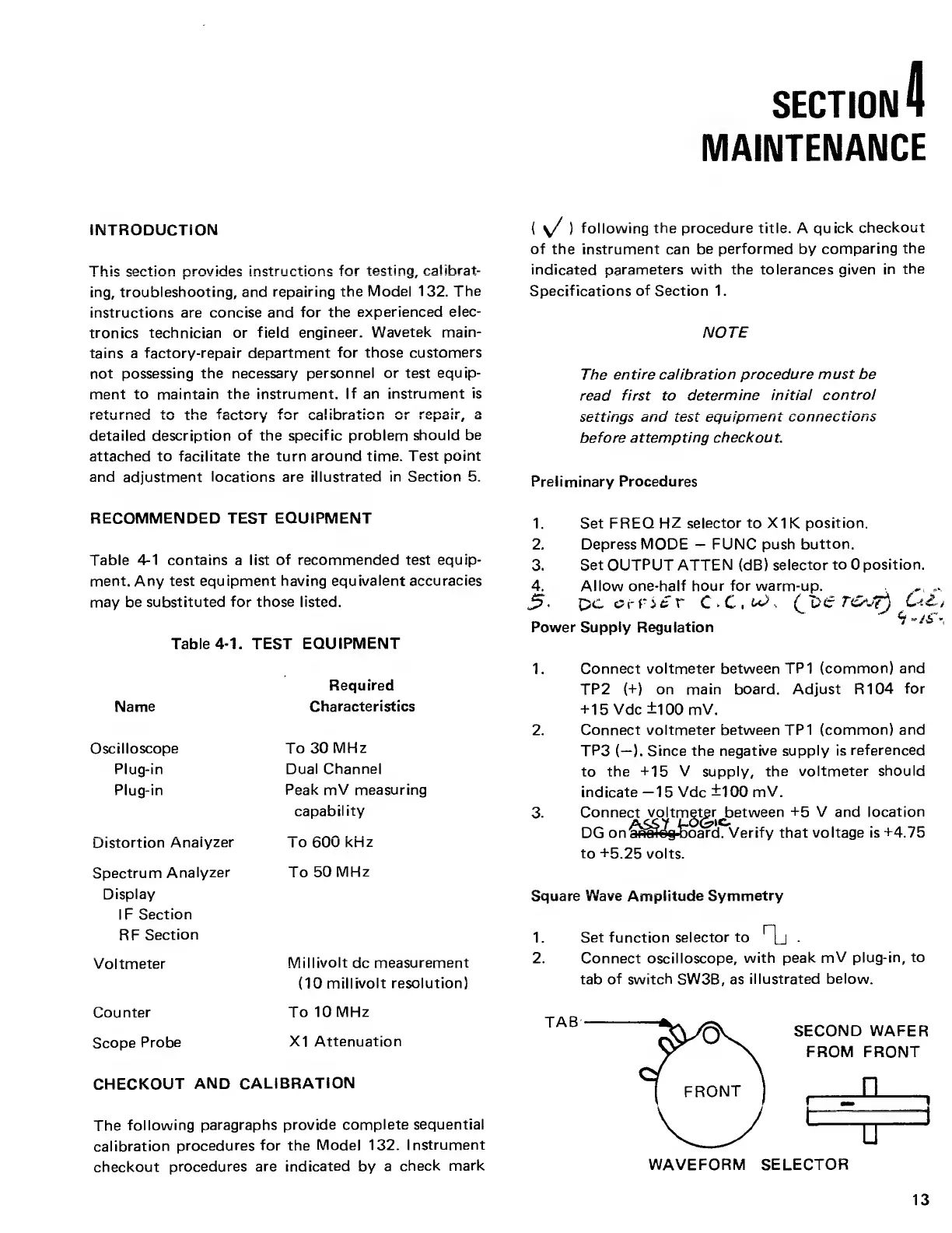
Square Wave Amplitude
Symmetry
1.
Set function selector
to
.
2. Connect oscilloscope,
with
peak mV
plug-in, to
tab
of switch
SW3B, as
illustrated
below.
Counter
To 10
MHz
Scope
Probe
XI
Attenuation
CHECKOUT
AND
CALIBRATION
The
following
paragraphs provide
complete sequential
calibration
procedures
for
the
Model 132.
Instrument
checkout
procedures
are indicated
by
a
check
mark
WAVEFORM SELECTOR
13