2.5.2 Operation as a
Voltage
Controlled Generator
The VCG input
connector can
be used to externally
control
the
frequency of the
generator. If
a
positive voltage
is
applied to
the
VCG
input
terminal the frequency
will
increase
from the dial setting. A
negative
voltage
will cause
the
frequency to
decrease from
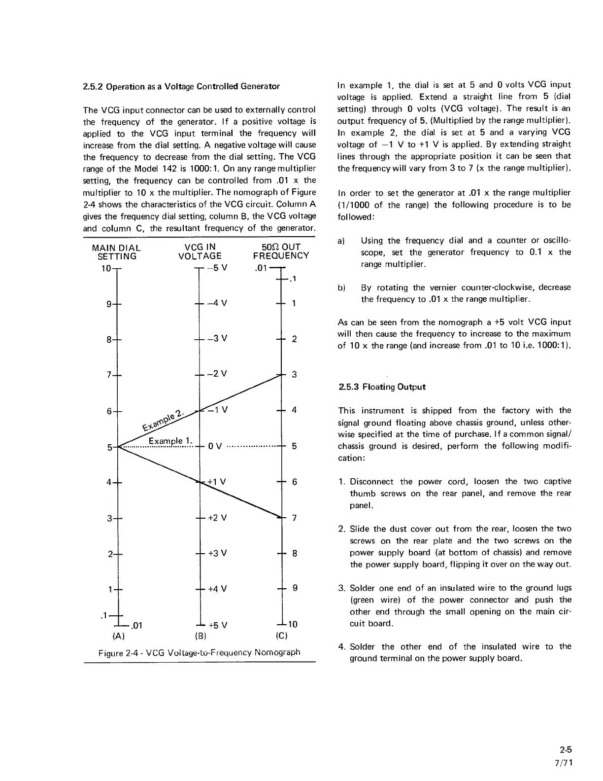
the dial setting. The VCG
range
of the Model 142 is
1000:1. On
any
range
multiplier
setting, the frequency
can be
controlled from .01
x the
multiplier to 10 x
the
multiplier. The nomograph
of Figure
2-4
shows the characteristics
of the VCG circuit.
Column A
gives the frequency
dial setting, column
B,
the
VCG
voltage
and
column
C,
the resultant
frequency of the generator.
MAIN
DIAL
VCG
IN
50fi
OUT
SETTING
VOLTAGE
FREQUENCY
In example
1,
the dial
is set at 5
and
0
volts VCG input
voltage
is applied.
Extend
a
straight
line from
5
(dial
setting)
through
0
volts (VCG
voltage).
The result is an
output
frequency of
5.
(Multiplied by
the range
multiplier).
In example
2,
the dial is set
at
5
and a
varying VCG
voltage of
-1
V to -M
V is applied. By
extending straight
lines through
the
appropriate
position it can be
seen that
the
frequency will vary
from 3 to
7
(x the
range
multiplier).
In order to set
the generator at .01
x the
range multiplier
(1/1000
of the range)
the
following procedure is to be
followed:
a)
Using the
frequency
dial and
a
counter
or oscillo-
scope,
set the
generator frequency to 0.1 x the
range multiplier.
b) By
rotating the vernier
counter-clockwise, decrease
the frequency to .01
x the range
multiplier.
As
can be seen from the
nomograph
a
-i-5
volt VCG input
will then
cause
the frequency to increase to
the maximum
of 10 X the range (and
increase from .01 to
10 i.e.
1000:1).
2.5.3 Floating Output
This instrument is shipped
from the factory
with the
signal ground
floating above chassis
ground,
unless other-
wise specified at
the time of purchase. If a common
signal/
chassis ground is desired,
perform the
following modifi-
cation:
1. Disconnect the
power
cord,
loosen
the two captive
thumb screws on
the rear panel, and
remove the rear
panel.
2. Slide the dust
cover
out
from
the
rear,
loosen the two
screws on
the
rear
plate and the two screws on
the
power supply board (at bottom
of chassis) and remove
the
power supply board, flipping
it over
on
the way out.
3. Solder one end
of
an
insulated wire to
the ground lugs
(green wire) of the power connector
and push the
other end through the
small opening on the main
cir-
cuit
board.
4. Solder the other end
of
the
insulated wire to
the
ground
terminal
on
the power supply board.
2-5
7/71