6. With
DC
OFFSET
set to 0 and SYMMETRY
control
set to NORM, the output waveform should
be a
symmetrical waveform
oscillating around
a
zero
dc
reference
point. (Except when in
a
positive
or nega-
tive pulse
position.)
7. Select
the polarity of
dc
offset
desired
using the
DC
OFFSET
switch, and
set the amount of offset
using
the MIN/MAX
control. If an
excessive
amount of dc
offset
is used, waveform
clipping may
be observed.
The
sum of peak
waveform voltage
and the dc offset
cannot exceed the
maximum
rated
output
of
the
generator.
For example, on the
0
dB attenuator
set-
ting the
maximum
output is 15 V peak-to-peak
or
7.5 V
peak above
and below zero
volts.
Offset
plus
peak voltage
cannot exceed 7.5 V. See Figure
2-2.
0 D.C.
OFFSET
NEGATIVE
DC OFFSET
Figure
2-2
-
DC
Offset
Control
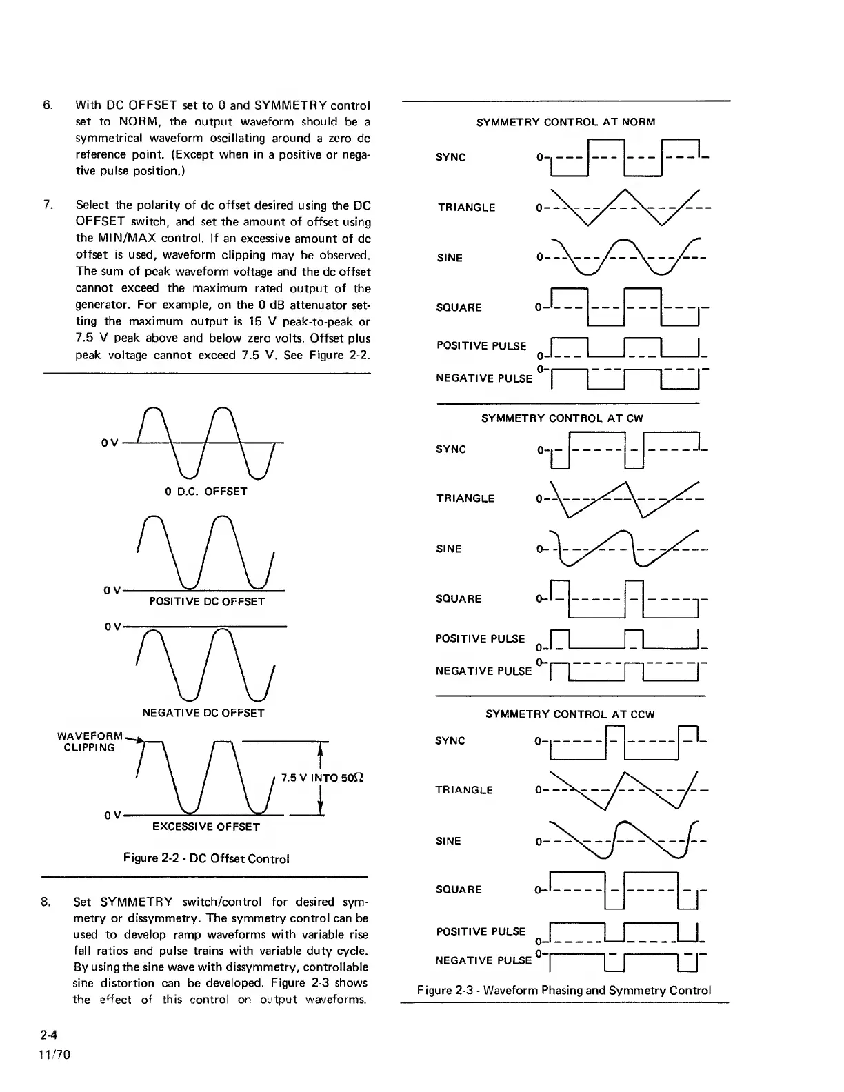
8. Set
SYMMETRY switch/control for desired
sym-
metry
or dissymmetry.
The
symmetry
control
can be
used to develop ramp
waveforms with
variable rise
fall
ratios and pulse trains with variable duty cycle.
By
using the sine wave
with
dissymmetry, controllable
sine
distortion can be
developed.
Figure
2-3
shows
the effect of this control on output
waveforms.
SYNC
SYMMETRY CONTROL
AT NORM
0
TRIANGLE
SINE
SQUARE
POSITIVE
PULSE
0
NEGATIVE
PULSE
SYMMETRY CONTROL AT CW
SYNC
TRIANGLE
SINE
SQUARE 0
-
POSITIVE PULSE
^
I
|_
NEGATIVE
PULSE
j
I
SYNC
SYMMETRY
CONTROL AT CCW
0-1
n_
r:::
TRIANGLE
SINE
SQUARE
POSITIVE PULSE
NEGATIVE PULSE
0-1
0-1
"
Figure
2-3
-
Waveform
Phasing
and Symmetry Control
2-4
1
1
/70