concise and
are
written for
the experienced electronics
technician or
field engineer having a working
knowledge
of this type of
instrumentation.
WAVETEK
maintains
a
factory repair department
for
those
customers not
possessing the necessary test equipment or
personnel
to
maintain this type of
instrument. If an
instru-
ment is returned to
the factory for calibration
or
repair,
a
detailed
description
of the specific problem should
be
attached. This will hasten turnaround time.
4.2.1
Recommended Test Equipment
The following
test
equipment
(or
equivalent)
is recom-
mended for this calibration procedure. A quick checkout
of the instrument can
be made by comparing the indicated
parameters with those given in the specifications
portion of
Section 1.
NOTE
The entire calibration procedure
must be read
first
to determine initial control settings and
test equipment
connections required before
attempting recaiibration. The
steps
of this
pro-
cedure should be performed in the sequence
given,
and the parts within
each step should
also be performed
in the sequence given.
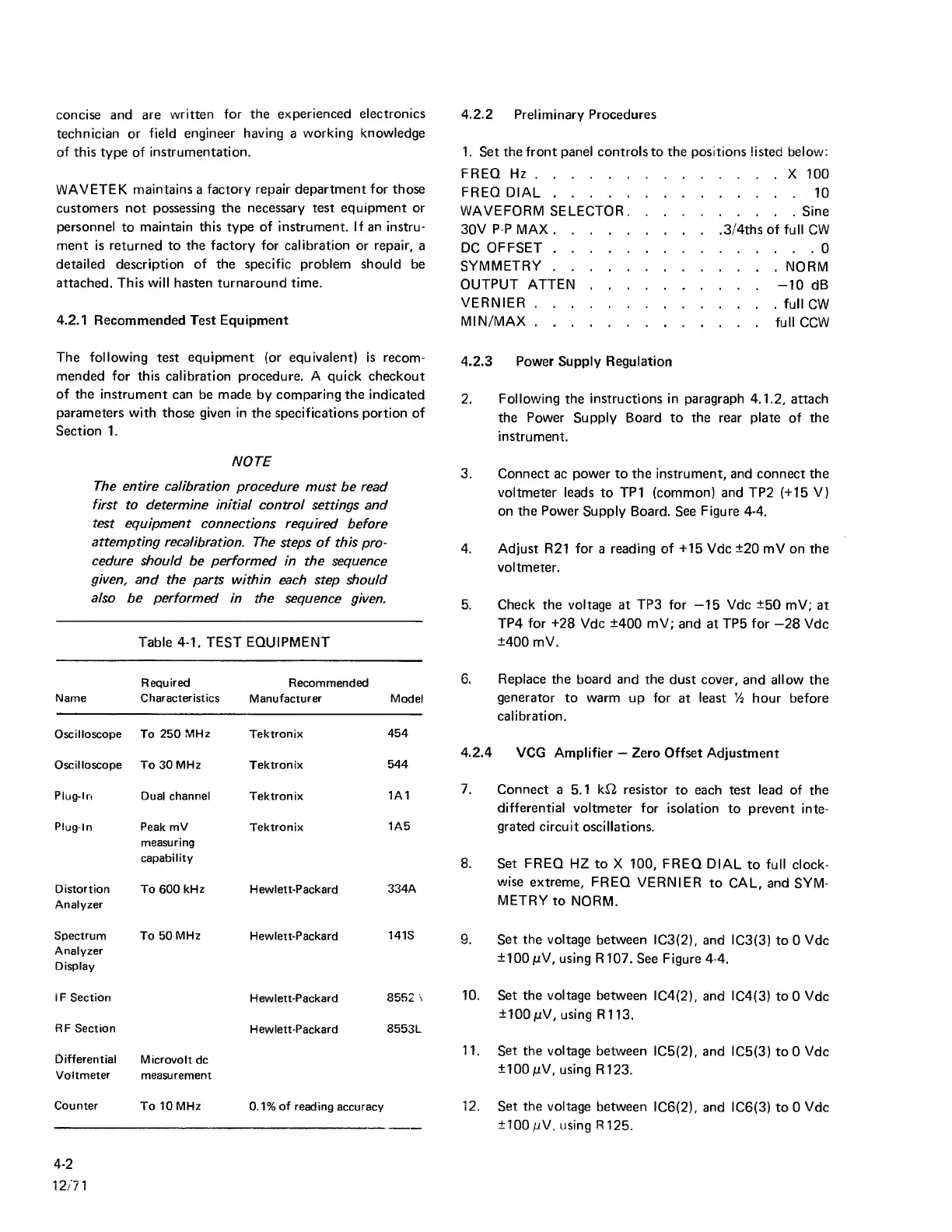
Table
4-1.
TEST
EQUIPMENT
Required Recommended
Name Characteristics
Manufacturer Model
Oscilloscope To
250
MHz
Tektronix
454
Oscilloscope To 30 MHz Tektronix
544
Plug-In
Dual
channel
Tektronix
1A1
Plug-In Peak mV
measuring
capability
Tektronix
1A5
Distortion
Analyzer
To 600
kHz
Hewlett-Packard
334A
Spectrum
Analyzer
Display
To 50
MHz
Hewlett-Packard
141S
IF Section
Hewlett-Packard
8552
\
RF
Section
Hewlett-Packard
8553L
Differential
Microvolt
dc
Voltmeter measurement
Counter
To 10
MHz
0.1%
of
reading accuracy
4.2.2
Preliminary Procedures
1.
Set the front panel controls to the positions listed below:
FREQ
Hz
X 100
FREQ
DIAL
10
WAVEFQRM
SELECTQR Sine
30V P-P MAX
3/4ths of full CW
DC
QFFSET
0
SYMMETRY
NQRM
OUTPUT ATTEN
-10
dB
VERNIER
full
CW
MIN/MAX
full CCW
4.2.3 Power Supply Regulation
2.
Following the instructions in paragraph
4.1.2,
attach
the Power Supply Board to
the
rear plate of the
instrument.
3. Connect ac power to the instrument, and connect the
voltmeter leads
to
TP1 (common) and TP2
(-M5
V)
on the
Power
Supply
Board. See
Figure
4-4.
4. Adjust R21 for a reading of
-t15
Vdc
±20
mV on the
voltmeter.
5. Check the voltage at TPS for
—15
Vdc ±50 mV;
at
TP4
for ±28
Vdc ±400 mV; and
at
TP5 for
—28
Vdc
±400 mV.
6. Replace the board and the
dust
cover,
and allow
the
generator
to warm up for
at
least
Vi hour before
calibration.
4.2.4
VCG Amplifier
—
Zero Offset Adjustment
7. Connect
a 5.1 ki2 resistor
to each test lead of the
differential voltmeter
for isolation
to prevent inte-
grated
circuit
oscillations.
8. Set FREQ
HZ to X
100,
FREQ
DIAL
to
full
clock-
wise extreme,
FREQ
VERNIER
to CAL, and
SYM-
METRY
to
NORM.
9.
Set the voltage
between IC3(2),
and IC3(3)
to 0
Vdc
±100
pV,
using R107.
See Figure
4-4.
10. Set the voltage between
IC4(2),
and IC4(3) to
0
Vdc
±100
/xV, using R1
13.
11. Set
the
voltage
between
IC5(2), and IC5(3)
to 0
Vdc
±100
mV,
using
R123.
12. Set the voltage
between
IC6(2), and
IC6(3) to 0 Vdc
±100
mV,
using R
125.
4-2
12/71