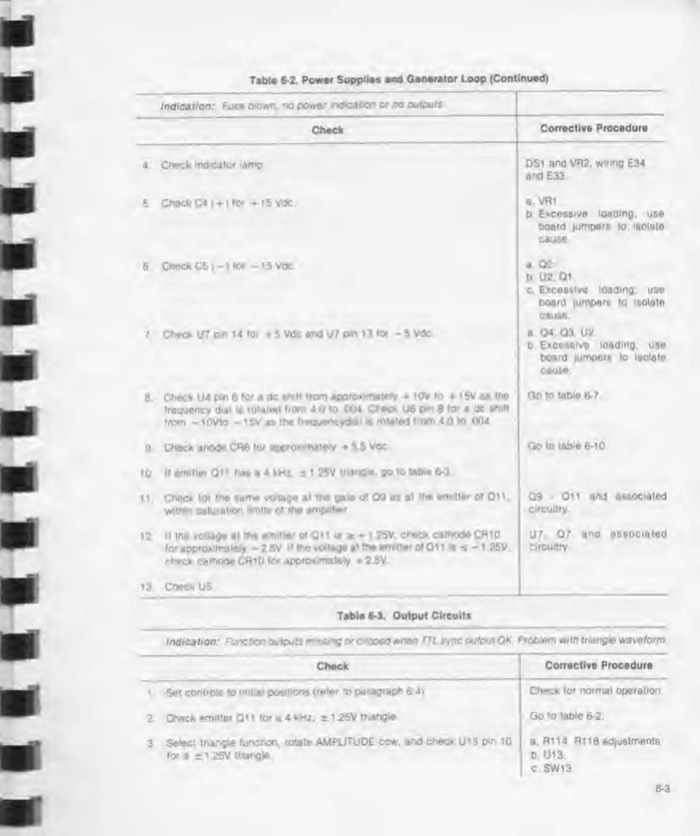
Table
6-2. Power
Supplies and Generator Loop
(Continued)
r
Indication:
Fuse clown. no
power indication
or
no outputs
Check
Corrective Procedure
4 Check indicator
lamp DS1
and VR2. wiring
E34
and E33
5. Check C4 ()
for + i5Vdc
a Vfli.
b
Excessive loading;
use
board lumpers to isolate
cause
6.
Check
C5(-)
tor -15 Vdc
a 02.
b U2,
01.
c.
Excessive loading; use
board jumpers to isolate
cause
7. Check U7
pm 14 tor
5
Vdc and
U7
pin 13
tor -
5 Vdc
a 04. 03. U2.
b
Excossive loading,
use
board
jumpers
to isolate
cause
8
Check
U4
pm
6
tor
a
dc shill
trom approximately
10V
to 15V as me
troquency
dial
is
rotated trom 4
0 to
.004 Check
U6
pm 8
lor
a dc
shitt
trom
-
lOVto
-
15V as
the treguencyd*ai is
rotated trom 4
0 to
004,
Go to
tobio 6-7.
9
Check anode CR6
tor approximately
3 5
Vdc Goto
table 6-10
10.
If
emitter
Oi 1
has
a
4 kHz. 1
1
25V triangle, go to
table 6-3
1 1 .
Check tor me same voltage at
the gate of
09 as
at the
emitter
ot Oi 1
.
within saturation
limits
ot
the amplifier
09-011 and associated
circuitry.
12 It
the voltage
at
the emitter ot Oil
is
t + 1 25V,
check cathode CR10
lor approximately
-
2.5V It the
voltage at the emitter ot Oi 1
1s
s
-
1 25V.
check cathode CRiO for
approximately
2 5V.
U7.
07
and
associated
circuitry.
13.
Check
U5
Table
6-3.
Output
Circuits
Indication: Function outputs
missing otcoped
when
TTL
sync output OK Problem with triangle waveform
Check
Corrective Procedure
1 . Set
controls to initial
positions (refer to
paragraph
6.4).
Check for normal operation.
2. Check emitter Qi 1 for a 4 kHz. ±
1 25V
triangle Go to table
6-2.
3.
Select triangle
function, rotate AMPLITUDE ccw. and
check
U13
pm
10
tor a
*
1 25V triangle
a.
R114 R1
18
adjustments.
b. U13.
c SW13.
6-3