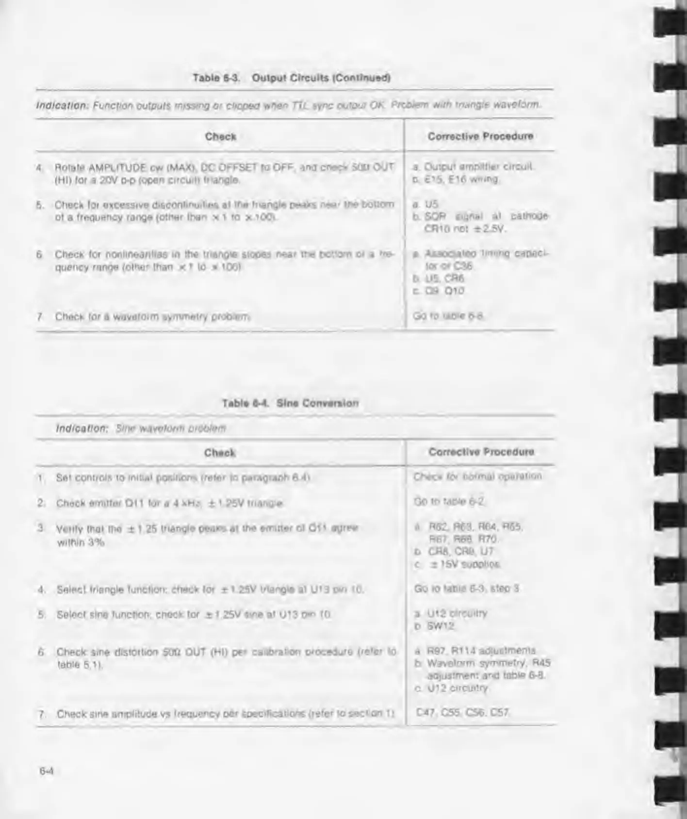
Table 6-3. Output Circuits (Continued)
Indication:
Function outputs
missing
or dipped wben TTL
sync
output
OK Problem with
triangle waveform
4
Check
Corrective Procedure
Rotate AMPLITUDE cw (MAX). DC
OFFSET to OFF. and check
500
OUT
(HI)
(or
a 20V p-p
(open circuit) triangle
a. Output
amplitier circuit
0. El
5.
E16
wiring.
5. Check (or excessive
discontinuities
at
the triangle
peaks
near the bottom
ol a trequency range
(other than
x 1 to x 100).
a U5
b SQR
signal
at
cathode
CRlOnot
±2 5V.
6.
Check lor nonlinearities in the
triangle
slopes
near the
bottom
of
a
tre-
quency range (other than x 1 to x 100)
a
Associated
timing capaci-
tor or
C36
b
U5.
CR6
c 09, 01
0
7
Check for
a
waveform symmetry problem Go
to table 6-8
Table
6-4. Sine Conversion
Indication: Sine waveform problem
Check
1 Set controls to
initial
positions
(refer
to
paragraph
6 4)
2. Check emitter Oil (or a 4 kHz,
±
1 25V triangle
3.
Von(y that the ± 1 .25
triangle peaks
at
the
emitter
ol 01 1
agree
within 3%,
4. Select triangle (unction; check for
±
1 25V
triangio
at
U1
3
pin 10
5.
Solect sine (unction; check (or
±
1 25V sine at U13 o*n
10.
Corrective
Procedure
Check lor
normal operation
Go to
table 6-2
a
R62. R63.
R64.
R65.
R67. R68. R70.
b CR8. CR9.
U7.
c. 1 15V suoplios.
Go
to table 6-3. step 3.
a
U12
circuitry
b SW12
6 Check sine
distortion
500 OUT (HI)
per calibration procedure
(refer
to
table
5.1).
a
R97. R114 adjustments,
b
Waveform
symmetry.
R45
adjustment and table 6-8
C U12
Circuitry
7
Check sine amplitude vs frequency
per specifications (refer
to
section 1
).
C47. C55. C56. C57