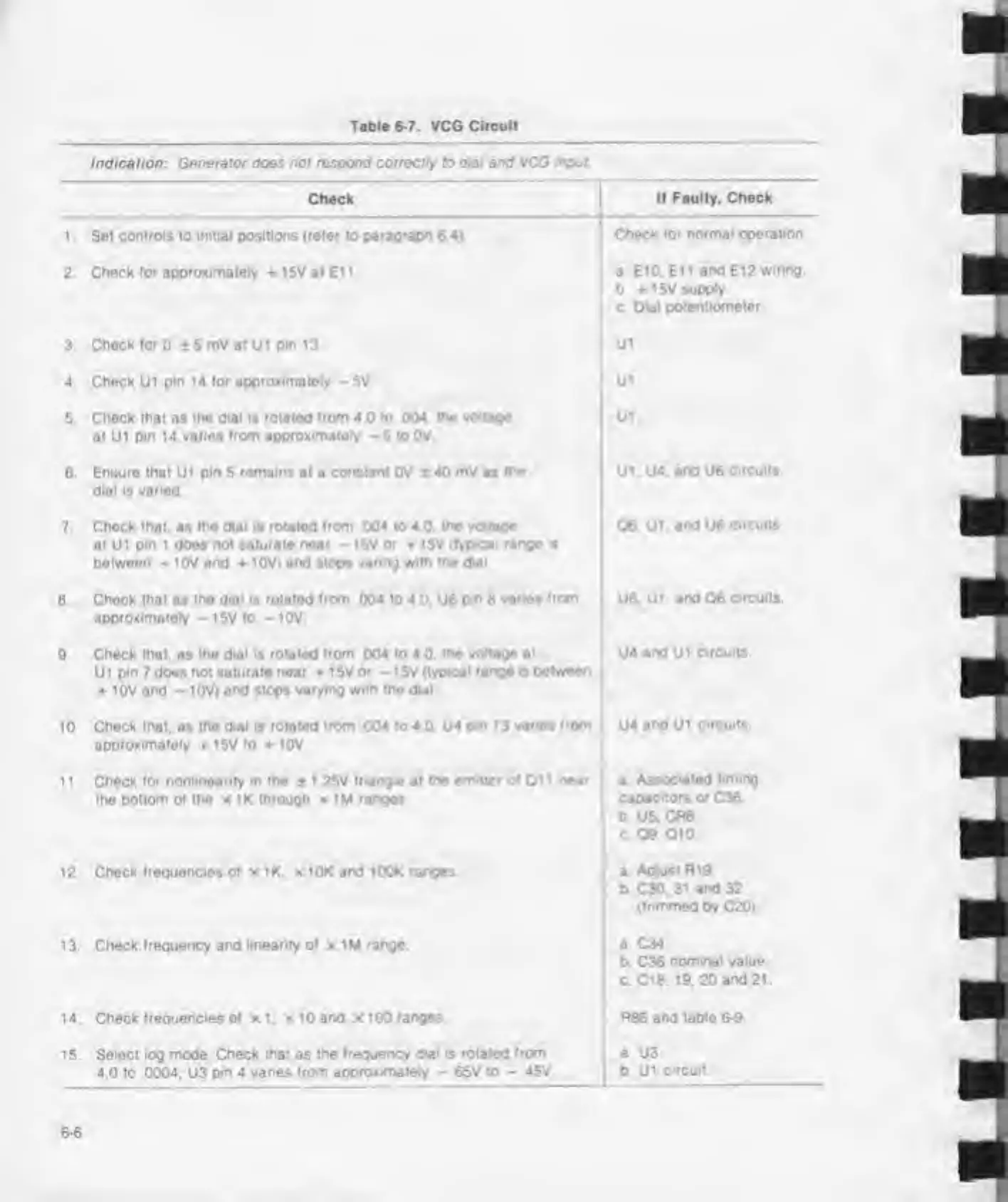
Table
6-7.
VCG
Circuit
Indication: Generator
does
nor respond correctly to dial
and
VCG
input
Check
1 . Sei
controls
to
initial positions (refer to paragraph
6
4>
2.
Check for approximately + 1 5V at E11
.
3
Check tor
0 ±5
mV at Ut
pin
13.
4 Check
U1
pin 14 for
approximately
-5V
5
Chock that
as
the dial is rotated from 4
0
to 004. me
voltage
at
U1
pm 14 varies from
approximately -
5 to 0V
6
Ensure that
Ui pm 5
remains
at a
constant
0V 2
40 mV as the
dial Is varied
7.
Check that,
as
the dial is rotated from 004
to
4
0.
the voltage
at
Ui pm 1
does
not saturate
near -
15V
or
15V
(typical range is
between
-
10V
and
10V)
and
stops
varng with
the
d>ai
8 Chock
that
as tho
dial is rotated from 004
to 4 0. U6 on 8
vanes from
approximately
-15V to
-
10V
9
Check that,
as
the
dial
is
rotated from
004 to
4
0. me
voltage at
Ui pin 7 does not saturate
near
15V o»
-
15V
(typical rango a
between
+ 10V
and
-
10V)
and stops varying w.tn
tho dial
10 Check
that,
as
the d.al
is
rotated from 004
to
4.0.
U4
pin 13 varies
from
approximately
15V
to
10V
1 1 .
Check for nonlinearity in the
±
1 25V
triangle
at
the emitter of 01 1 near
the bottom of the x IK
through
x 1M
ranges
12. Check
frequencies
of x IK. x 10K
and
100K
ranges
13.
Check frequency and linearity of x 1M
range
14
Check frequencies of xl.
x
10 and x 100 ranges
15. Select log mode. Check
that
as
the frequency dial is rotated from
4 0 to .0004. U3
pm 4 varies from approximately
-
65V to
-
45V
If Faulty. Check
Check for normal operation
a
ElO. Ell
and
E12
wiring
b 15V
supply
c.
Dial potentiometer
UI.
UI.
UI.
ui.
U4.
and
U6
circuits
06. Ui.
and
U6
circuits
U6.
Ui.
and
06
cifcuits
U4
and
UI
circuits
U4
and Ui circuits
a Associated
timing
capacitors or
C36
b US. CR6
c
09.010
a
Adjust Ri9
b C30. 31
and
32
(trimmed by
C20).
a C34
b C36
nominal value
c. C18. 19. 20
and 21
RB6 and
table 6-9
I
a U3
b
UI circuit.