Table
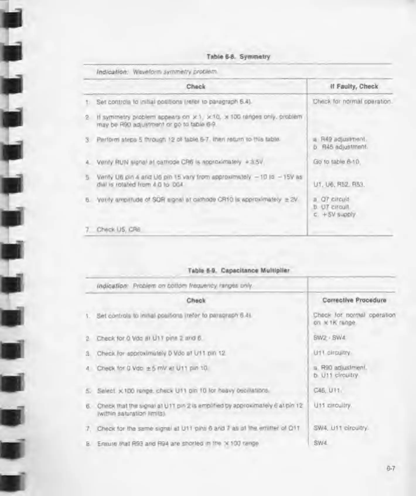
6-8. Symmetry
Indication:
Waveform symmetry problem
Check
1.
Set controls to
initial positions (refer to paragraph 6.4).
2. II symmetry
problem appears on
x 1.
x
10.
x 100 ranges only, problem
may be R90
adjustment
<x
go to
table
6-9
3
Perform steps
5
through 12 of
table
6-7.
then return
to
this table
4, Verify RUN
signal
at
cathode CR6
*
approximately +3 5V
5,
Verify
U6
pin 4 and
U6
pm 15 vary from
approximately -
10 to
-
15V as
dial
is rotated from 4
0 to
004.
6.
Verify amplitude of
SOR
signal at cathode CfliO is approximately
± 2V
7. Check U5.CR6
Table
6-9.
Capacitance Multiplier
Indication:
Problem
on
bottom frequency ranges only.
Check
1 .
Set controls to
initial positions (refer to paragraph 6.4).
2.
Check for
0 Vdc
at Ui
1
pms 2
and
6
3.
Check for
approximately
0 Vdc at Ull
pin 12
4.
Check for
0 Vdc ± 5
mV at Ui
1
pin 10.
5.
Select x 100
range,
check Ui 1 pin
10 for heavy oscillations.
6. Check
that the signal
at U 1
1
pin
2
is ampif
red by
approximately
6
at pin 1
2
(within saturation limits).
7.
Check for the same signal at Ui
1
p«ns 6
and
7 as at
the emitter of
01
1
8.
Ensure that R93 and R94 are
shorted in the
x 100
range
If
Faulty,
Check
Check for normal operation
a
R49 adjustment.
b. R45
adjustment.
Go to table 6-10.
UI. U6. R52. R53.
a
07 circuit
b U7
circuit.
c. + 5V
supply
H-
—
Corrective Procedure
Chock
for normal operation
on
x
IK range
SW2
-
SW4.
U11
circuitry
a R90
adjustment,
b. U11
circuitry.
C46. U11.
Ui 1 circuitry.
SW4. U11
circuitry.
SW4.