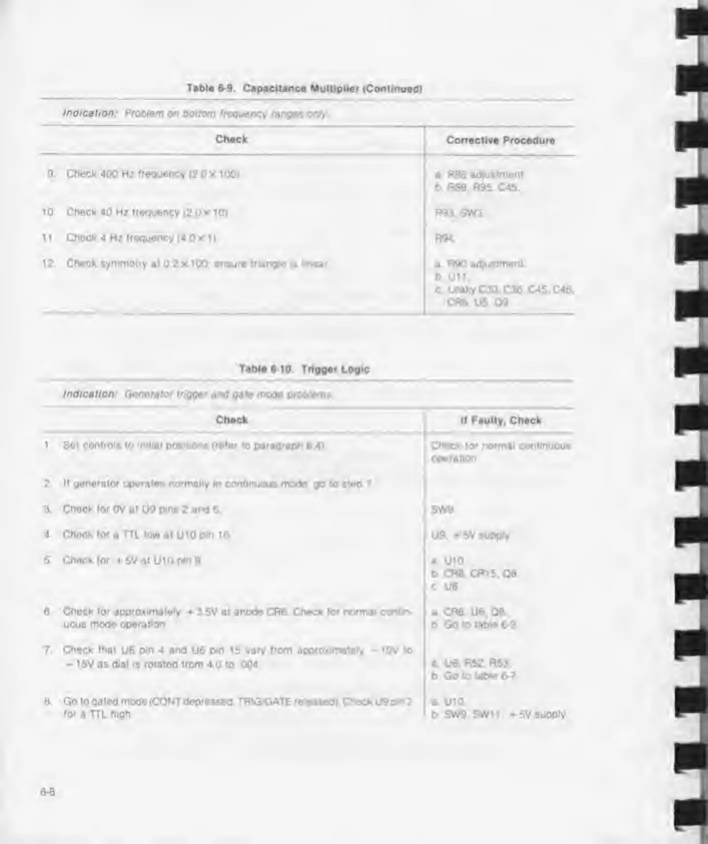
Table
6-9.
Capacitance Multiplier
(Continued)
Indication:
Problem on Bottom frequency ranges onr,
Check
9
Check
400 Hz
frequency
(2 0
X 1
00)
1
0
Check 40 Hz frequency
(2.0
x 1
0)
1 1
Chock 4
Hz
frequency
(4 0 x t
)
12 Check symmetry at
0.2 x 100
ensure triangle is linear
Table
6 10. Trigger Logic
Indication:
Generator
logger and gate mode problems
Check
t Sot controls to initial positions (refer
to
paragraph
6 4)
2,
II generator operates normally in continuous
mode go to steo 7
3,
Check for
0V at U9 pins
2
and
5
4 Check for
a
HL low at
U 10
pm 10
5. Chock
lor
+ 5V at
U10
pin
9
6.
Chock for approximately
3 5V
at anode
CR6
Check
for
normal contin-
uous mode operation
7 Check that
U6
pin 4 and
U6
pin
15
vary from approximately -
tOV to
-
t5V as
dial
is rotated from 4
0
to 004
8 Go to gated mode (CONT
depressed.
TRIG/GATE released) Check U9p*n
2
for a TTL high.
Corrective Procedure
a
R86 adjustment,
b R89. R95.
C45.
R93. SW3
R94
a R90
adjustment.
0
Utt
c Leaky C30.C36 C45.C46.
CR6.
U5. 09
II Faulty. Check
;
Check for normal continuous
operation
SW9.
U9. 5V
supply
a U
10
0 CR6. CR15.08
c.
U6
a CR6. U6. 08
b Go
to table 6-2
a U6. R52. R53.
b Go to
table
6-7
a.
U
10
b SW9. SWil. *5V
supply