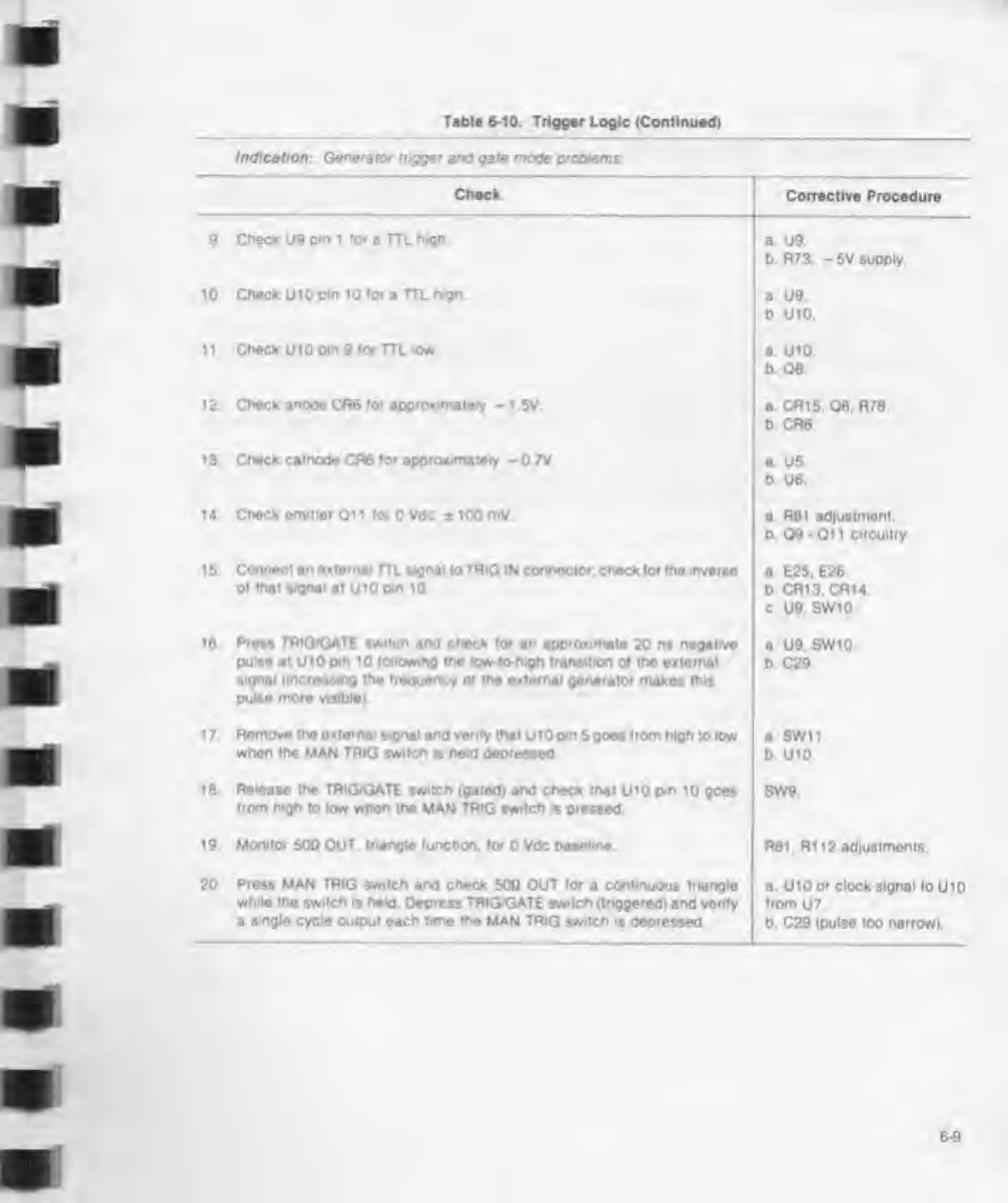
Table
6-10.
Trigger Logic (Continued)
Indication:
Generator
trigger and gate mode problems
Check
9.
Check
U9
pm 1 for
a TTl
high.
10. Check
U10
pm 10 for
a
TTL high.
11. Check
U10
pm
9
for TTL
low
1
2.
Check
anode
CR6 for approximately
-
1 ,5V
1 3. Check
cathode CR6 for approximately -
0.7V.
14 Check omutor Qi i for
0 Vdc *
100 mV
1 5. Connect
an external
TTL signal lo TRIG IN connector; check for the inverse
of
that signal
at UlOpin 10.
16 Pross TRIGfGATE switch and check lor
an approximate
20
ns negative
pulse
at U10
pin
10
following the low-tomigh
transition of the external
signal (increasing the frequency of the external generator
makes this
pulse more visible)
1
7.
Remove the external signal and verify that
U 10
pm
5
goes
from high
to
low
when
the MAN TRIG switch is
held
depressed
18
Release the
TRIG/GATE switch (gated) and check that
U10
pin
10 goes
from high
to
low when
the MAN TRIG
switch
is pressed
19 Monitor
50Q OUT.
triangle function, for
0
Vdc baseline
20
Press MAN TRIG switch and check
50Q OUT
for
a continuous triangle
while the switch is held. Depress TRIG/GATE switch (triggered)
and verify
a
single
cycle output each time the MAN TRIG switch is depressed
Corrective Procedure
a.
U9
b. R73.
-
5V supply.
a.
U9.
b U10.
a. U10.
b Q8
a. CR15. 08. R78.
b. CR6.
a. U5.
b. U6
a
R81 adjustment.
b. 09-011 circuitry
a
E25. E26.
b CR13, CR14.
c.
U9.
SW10
a U9. SW10.
b C29
a SW11
b.
U10.
SW9.
R81. R112 adjustments.
a.
UlOor clock
signal loUlO
from
U7.
b. C29
(pulse
too
narrow).