Model 9100 — Operator's Guide: Capacitance Function 13-1
User's H'b'k
Page Ref
13
Capacitance Calibration
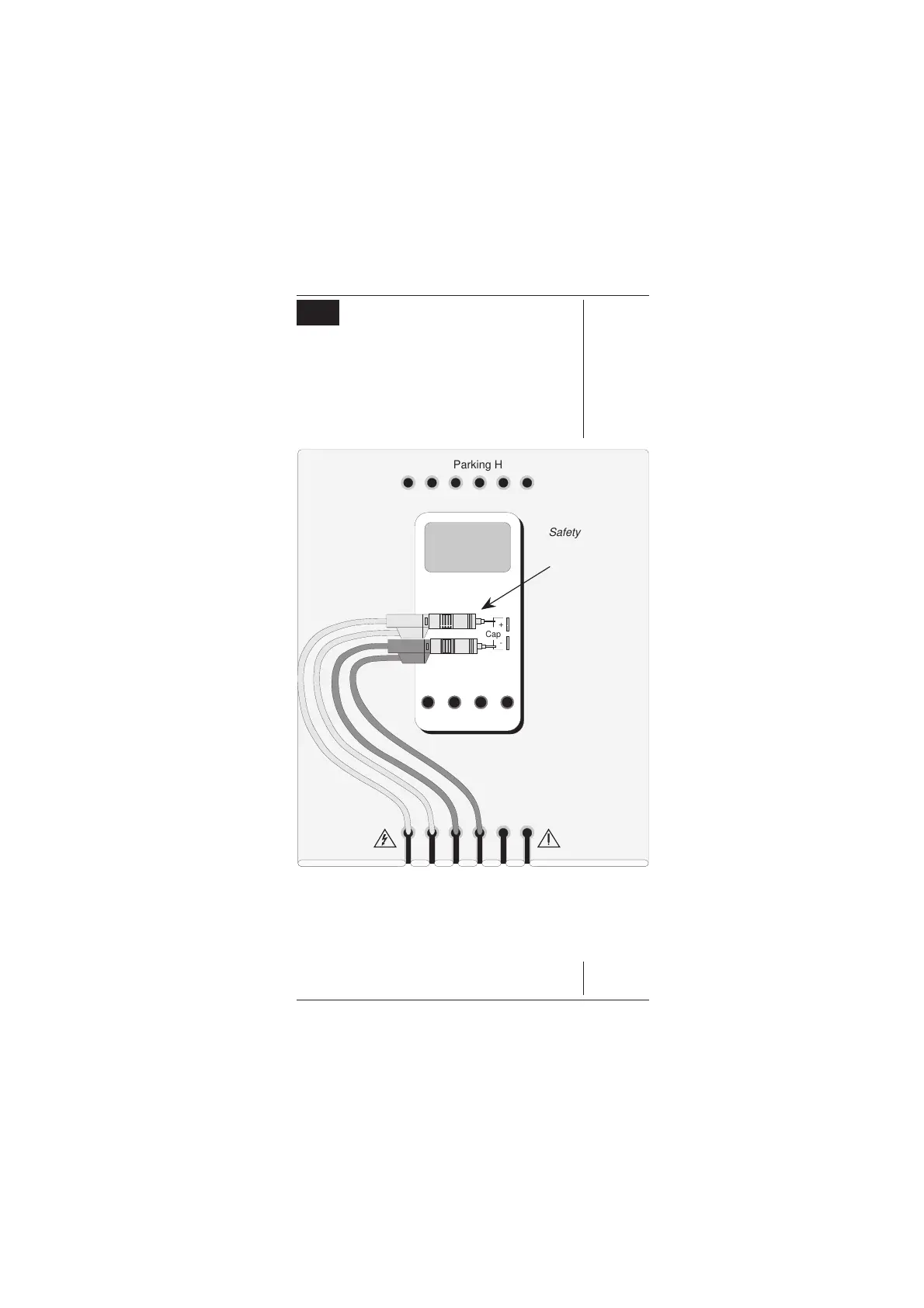
13.1 Interconnections
The general connection scheme for UUT calibration
is illustrated in
Fig. 13.1
. The use of either 4-wire
remote sensing at the UUT terminals, or 2-wire local
sensing at the 9100 terminals, is served by the same
connections from the 9105 at the work mat. Selection
of 2/4-wire is carried out on the 9100 front panel.
Fig. 13.1 Connections for
4-Wire or 2-Wire Capacitance UUT Calibration
(Leads which are not shown are not connected)
10A mA COM V-
Cap
+
-
K-type
+
-
Safety Bananas
Terminated with
Probe Adaptors.
For those UUTs on
which one of the
capacitance terminals
is marked with a '+'
sign, always observe
the correct polarity as
shown. If no terminal
is marked '+', try
reversing the
connections, and then
use the least-noisy
arrangement.
Some UUTs use
standard safety
banana sockets for
Capacitance
measurement. In
these cases the
adaptors will not be
required
Adaptor Parking Holes
Work Mat
UUT
I+mAI+ 20ALI-
sLsHH
WhiYellBlkBlkRedRed
www.valuetronics.com