Model 9100 — Operator's Guide: Thermocouple Function 14-1
User's H'b'k
Page Ref
14
Thermocouple
Temperature Calibration
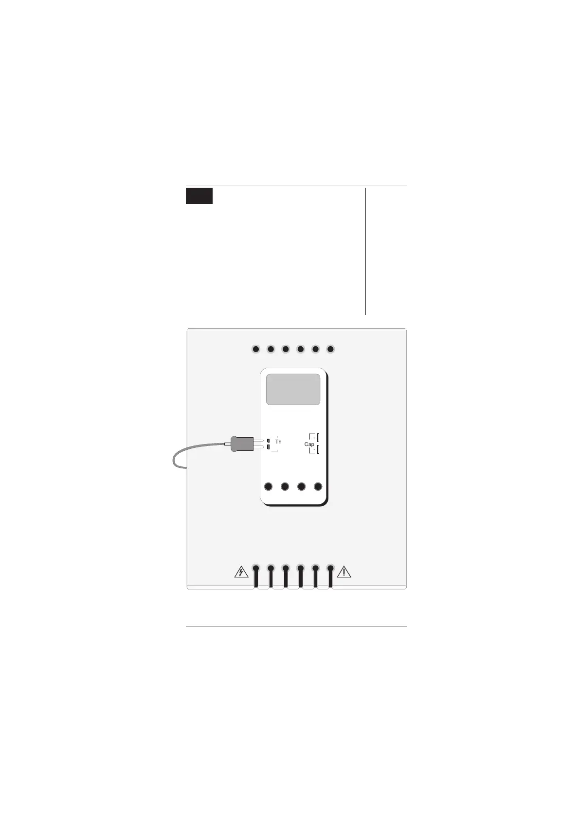
14.1 Interconnections
The general connection scheme for UUT calibration
is illustrated in Fig. 14.1. Always use the correct
extension cable from the Thermocouple socket on
the 9105 to the UUT Thermocouple input. Observe
the correct polarity, otherwise spurious junctions
may be set up.
Fig. 14.1
Connections for Thermocouple Temperature Calibration
N.B. Always ensure that the CJC pod fitted to the
leadset connection block (or 9100 front panel)
is the same unit that was calibrated together
with the 9100 unit in use.
10A mA COM V-
Cap
+
-
Thermo
Couple
+
-
+
Connect both ends in
correct orientation;
The 2mm blade is the
'+' contact.
On most UUTs, the
plug/socket
connection is unique
and cannot be
wrongly connected
Always use the correct
thermal extension
connector from the
isothermal block
I+mAI+ 20ALI-sLsHH
WhiYellBlkBlkRedRed
Adaptor Parking Holes
Work Mat
UUT
www.valuetronics.com