Model 9100 — Operator's Guide: RTD Temp. Function 15-1
User's H'b'k
Page Ref
15
RTD Temperature
Calibration
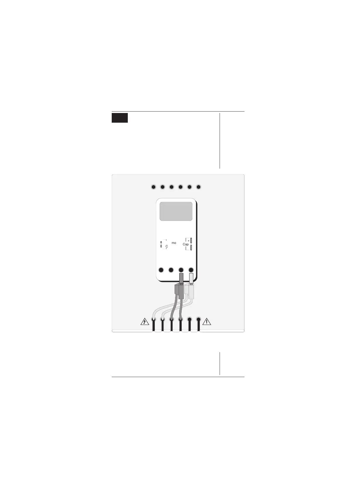
15.1 Interconnections
The general connection scheme for UUT calibration
is illustrated in
Fig. 15.1
. The use of either 4-wire
remote sensing at the UUT terminals, or 2-wire local
sensing at the 9100 terminals, is served by the same
connections from the 9105 at the work mat. Selection
of 2/4-wire is carried out on the 9100 front panel.
Fig. 15.1
Connections for RTD Temperature Calibration
10A mA COM V-
Cap
+
-
I+mAI+ 20ALI-
sLsHH
WhiYellBlkBlkRedRed
Adaptor Parking Holes
Work Mat
UUT
Thermo
Couple
+
-
www.valuetronics.com