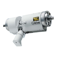
Top
section
Int.
section
track
Tighten
5/16”-18
Hex nut
Top
fixture
slide
Top
section
(1)1/4”-20
Track bolt and
(1) 1/4”-20
flange hex nut
Strut
13A
13B
13C
13D
track
Track
roller
13A
13C
Top fixture
slide
Tighten the
5/16”-18
Hex nut
To
Top section
Intermediate
section
13B
Attaching Inside Lock
Tools Required: Power drill, 7/16” Socket driver, Tape measure, Safety glasses,
Leather gloves
14
14A
Inside lock
End cap
1/4”-20 x 11/16”
Self drilling screws
Square hole in
vertical track
Lock
(Second)
section
14B
1/8”
9100 / 9405 /
9600 / 5120 /
5145 / 9800 only.
Second section
1/8”
Inside
lock
End cap
(4) 1/4”-20 x 11/16”
Self drilling screws
Striker
plate
Vertical
track
(2) 1/4” - 20 x
9/16” Track bolts
and (2) 1/4” - 20
Flanged hex Nuts
Inside
lock bar
14A
14B
14E
14D
14C
9700 anbd 9510 only.
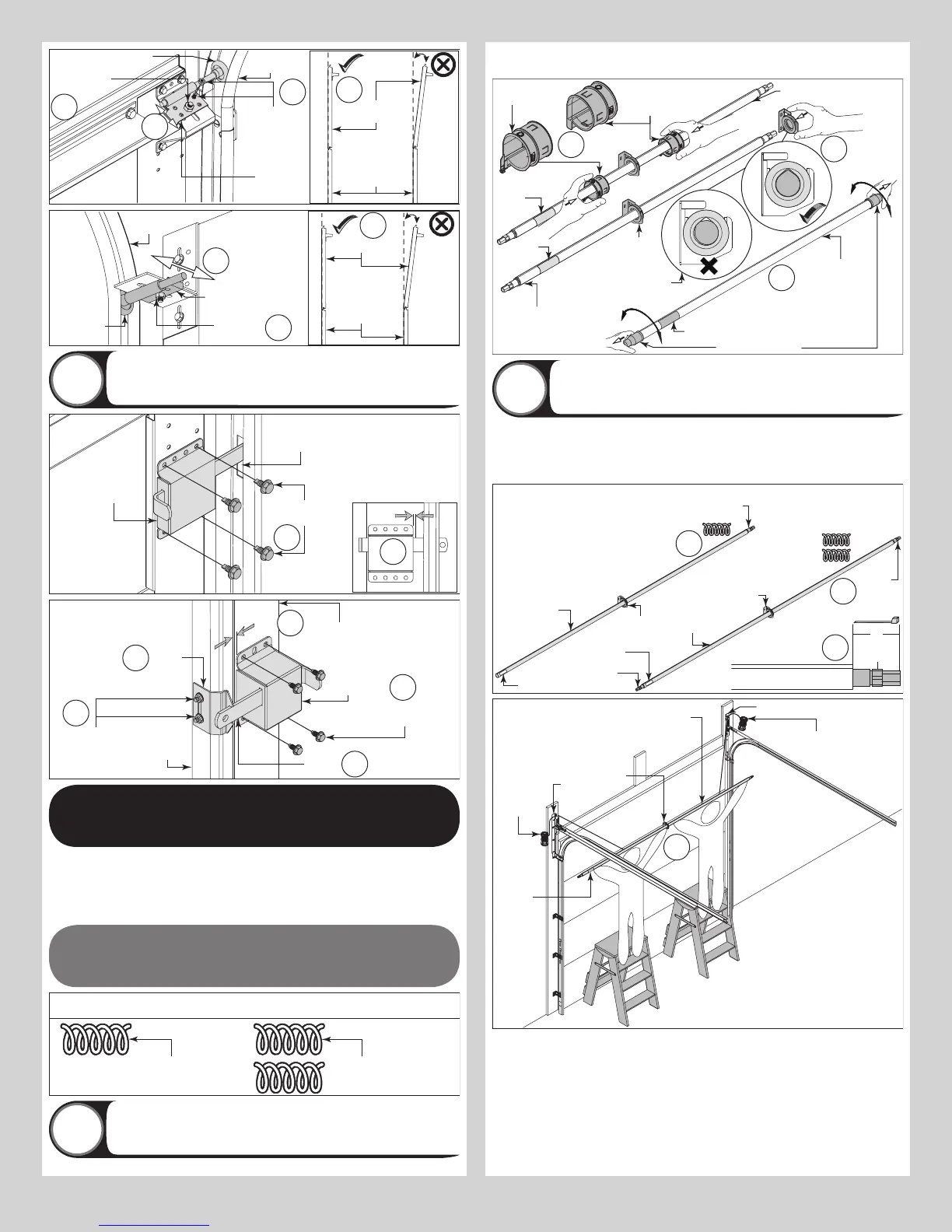
COUNTERBALANCE
INSTALLATION INSTRUCTIONS
NOTE: Refer to parts breakdown, to determine what type of counterbalance you have.
NOTE: If your door has TorqueMaster
®
Springs, proceed to Step A1.
NOTE: If your door has Torsion Springs, proceed to Step B1.
NOTE: If your door has Extension Springs, proceed to Step C1.
TORQUEMASTER
®
SPRING
Single Spring
Applications
Double Spring
Applications
NOTE: Some graphics in “A” are designated as either single spring applications or double
spring applications.
Preparing The TorqueMaster
®
Spring Tube
Assembly
Tools Required: Safety glasses, Leather gloves
A1
NOTE: TorqueMaster
®
springs come lubricated and pre-assembled inside the TorqueMaster
®
spring tube.
TorqueMaster
®
spring
tube
Remove shipping
Label
A1a
Left hand drum
wrap (Optional)
Right hand
drum wrap
(Optional)
A1b
A1c
Label
Label
TorqueMaster
®
spring tube
TorqueMaster
®
spring tube
Center
bracket
NOTE: Orient profile of
spring tube and center
bracket hole for smooth fit.
Installing Cable Drum Assemblies
Tools Required: Tape measure, Step ladder, Safety glasses, Leather gloves
A2
NOTE: Cable drum assemblies are marked right and left hand. Cable drums and TorqueMas-
ter
®
spring tube assembly are cam shaped to fit together only one way.
NOTE: Temporarily support the center of the TorqueMaster
®
spring tube assembly until the
center bracket is installed in step A4.
5”
Center
bracket
Winding
shaft
Winding
shaft
Winding
shaft
Winding
shaft
TorqueMaster
®
spring tube
Center
bracket
Label
Label
TorqueMaster
®
spring tube
A2a
A2a
A2b
TorqueMaster
®
spring tube
NOTE: For single spring applications,
there will be no left hand spring in the
TorqueMaster
®
spring tube assembly.
NOTE: If winding shaft is not visible out
of the right hand side, gently shake the
TorqueMaster
®
spring tube until
winding shaft sticks out 5”.
NOTE: If both winding shafts are
not visible, gently shake the
TorqueMaster
®
spring tube until
both winding shaft sticks out 5”.
Left hand
cable
drum
assembly
Right hand cable
drum assembly
NOTE: Working with a partner as needed, lift
the TorqueMaster
®
spring tube assembly up
and rest it on top of the flag angles.
Flag
angle
Center
bracket
Label
A2c
FOR SINGLE SPRING APPLICATIONS:
IMPORTANT: ENSURE THE SNAPS ON THE IDLER BRACKET (LEFT HAND SIDE) ARE EN-
GAGED INTO THE LEFT HAND CABLE DRUM, SO THAT IT DOES NOT COME BACK OUT.
NOTE: The idler bracket is designed for permanent assembly. Do not attempt to remove idler
bracket once inserted into the cable drum.
NOTE: The idler bracket must extend past the cable drum far enough to expose the groove.
Align the idler bracket groove with the round notch in the flag angle.
10