Counterbalance
lift cable
Left hand cable
drum assembly
Counterbalance
lift cable
Cable loop
Bottom
section
Cable loop
Bottom corner
bracket
warning label
Bottom corner
bracket
warning label
Right hand cable drum assembly
End cap
Left hand cable
drum assembly
Bottom
section
Counterbalance
lift cable
cable
drum
assembly
Counterbalance
lift cable
Bottom corner
bracket
warning label
Bottom
weather
seal
Cable
loop
Short stem
track roller
Bottom corner
bracket
Milford
pin
(3) 1/4”-20 x 11/16”
Self drilling screws
(RED HEAD )
Roller
spacer
Bottom
section
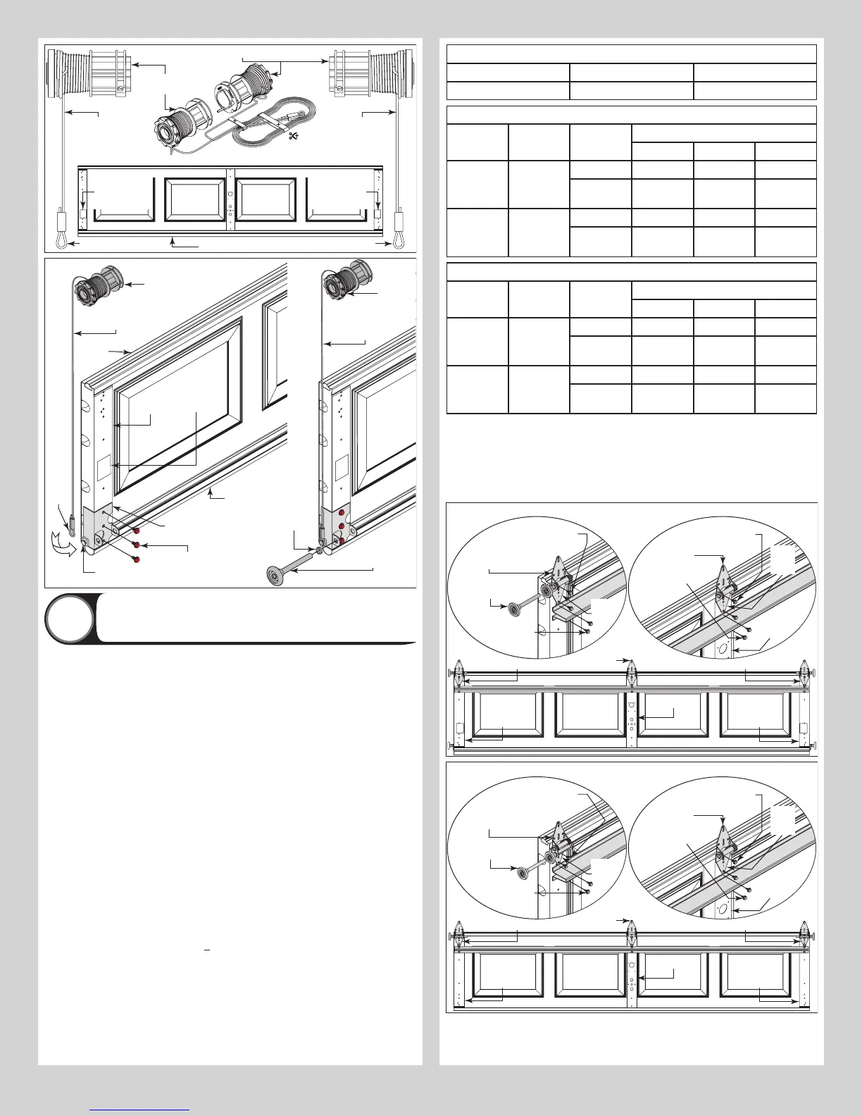
Attaching Hinges and Strut(s) To Sections
3
NOTE: Refer to door section identification, located in the pre-installation section of this
manual.
NOTE: The graduated hinges can be identified by the number stamped on the lower hinge
leaf.
NOTE: The #1 graduated end hinges serves as end hinges on the bottom section. The #1
graduated end hinges also serves as center hinges on all sections, except for the top section.
NOTE: The #2 graduated end hinges serves as end hinges on the Lock section.
NOTE: The #3 graduated end hinges serves as end hinges on the Intermediate I section.
NOTE: The #4 graduated end hinges serves as end hinges on the Intermediate II section.
ATTACHING HINGES TO SECTIONS:
Starting on the left hand side of the bottom section, align the lower hinge leaf of the #1
graduated end hinge over the holes, located at the top of the end caps. Attach lower leaf to
the end caps with (2) 1/4” - 14 x 5/8” self tapping screws. Repeat for other side. Next, align
the lower hinge leaf of the #1 center hinges with the pre-punched holes at each center stile
location(s), located at the top of the bottom section. Attach lower hinge leaf to the center stile
with (2) 1/4” - 14 x 5/8” self tapping screws.
IMPORTANT: ONCE THE 1/4” - 14 X 5/8” SELF TAPPING SCREWS ARE SNUG AGAINST THE
LOWER HINGE LEAVES, TIGHTEN AN ADDITIONAL 1/4 TO 1/2 TURN TO RECEIVE MAXIMUM
DESIGN HOLDING POWER.
ATTACHING STRUT(S) TO SECTIONS: Using the strut schedule, determine the placement
of the struts for your door width and door height.
INSTALLATION ON THE TOP SECTION: Locate and center the strut at the top of the top
section surface. Secure strut to top section using (2) 1/4” - 20 x 7/8” self drilling screws at
each end and at each center stile locations.
INSTALLATION ON ALL OTHER SECTIONS: Locate and center the strut onto the section
surface and up against the bottom of the hinges. Center the strut side to side. Secure strut
to the section using (2) 1/4” - 20 x 7/8” self drilling screws at each end and center stile
locations.
NOTE: All struts are placed at the top of the sections and up against the bottom of the gradu-
ated hinges, for the intermediate, lock and bottom sections.
Strutting Schedule Key:
TS = Top Section I1 = Intermediate Section #1 BS = Bottom Section
I2 = Intermediate Section #2 LS = Lock Section ES = Every Section gets a strut.
Strutting Schedule For Models 8000 and 8100
Door Heights Section Qty Section Type Door Widths
14’0” - 16’0” 17’0” - 18’0” 20’0”
6’0” - 7’0” 4 Solid (1) TS (3) TS, LS, BS ES
Windows (1) TS (1) 3” TS, (2)
2” LS, BS
ES
7’6” - 8’0” 5 Solid (2) TS, BS (3) TS, I1, BS ES
Windows (1) 3” TS, (1)
2” BS
(1) 3” TS, (2)
2” I1, BS
ES
Strutting Schedule For Model 8200
Door Heights Section Qty Section Type Door Widths
14’0” - 16’0” 14’0” - 16’0” 14’0” - 16’0”
6’0” - 7’0” 4 Solid (2) TS, BS (3) TS, LS, BS ES
Windows (1) 3” TS, (1)
2” BS
(1) 3” TS, (2)
2” LS, BS
ES
7’6” - 8’0” 5 Solid (2) TS, BS (3) TS, I1, BS ES
Windows (1) 3” TS, (1)
2” BS
(1) 3” TS, (2)
2” I1, BS
ES
Insert a short stem track roller into the hinge tube of the #1 graduated end hinges. Repeat
graduated hinge attachment using the appropriate graduated end hinges for all remaining
sections except the top section.
IMPORTANT: WHEN PLACING SHORT STEM TRACK ROLLERS INTO THE #2 GRADUATED
END HINGES AND HIGHER, THE SHORT STEM TRACK ROLLER GOES INTO HINGE TUBE
FURTHEST AWAY FROM SECTION.
#1Center
hinge(s)
#1 Graduated
end hinge
Lower
hinge
leaf
Short stem
track roller
Center stile(s)
End stile
End stile
Bottom
section
#1Center
hinge(s)
#1 Graduated end hinge#1 Graduated end hinge
Center
stile(s)
Lower
hinge
leaf
1/4”-14 x 5/8” Self
tapping scews
1/4”-14 x 5/8”
Self tapping scews
1/4”-20 x 7/8”
Self drilling
screws
1/4”-20 x 7/8”
Self drilling
screws
NOTE: Depending on your door some sections may or may not require a strut to be installed
onto the section.
Strut
Strut
Center stile(s)
End stile
End stile
Lock
section
#1Center
hinge(s)
#2 Graduated end hinge#2 Graduated end hinge
#1Center
hinge(s)
#2 Graduated
end hinge
Lower
hinge
leaf
Short stem
track roller
Center
stile(s)
Lower
hinge
leaf
1/4”-14 x 5/8” Self
tapping scews
1/4”-14 x 5/8”
Self tapping scews
1/4”-20 x 7/8”
Self drilling
screws
1/4”-20 x 7/8”
Self drilling
screws
NOTE: Depending on your door some sections may or may not require a strut to be installed
onto the section.
Strut
Strut
7