Vertical
track
assembly
Jamb
bracket
Flag
angle
Flag angle lag screw locations
5/16” x 1-5/8”
Lag screws
Bottom
section
Track
rollers
12R FA
3/8” to 5/8”
Spacing
Bottom section
15R QI12R QI
Floor
Track roller
15R FA
Vertical track
Attaching Top Fixtures To Top Section
8
Starting on the left hand side, align the upper-center hole of top fixture base with the hole
in the end stile of the top section or below strut (if applicable) and even with the edge of the
top section, as shown. The slotted half of the top fixture base should be facing upwards.
Fasten to section using (4) 1/4” - 20 x 11/16” self drilling screws. The top fixture slide will be
tightened and adjusted later, in step, Adjusting Top Fixture. Insert short stem track roller into
top fixture slide. Repeat same process for other right hand side.
NOTE: The top fixture slide will be tightened and adjusted later, in step, Adjusting Top Fixture.
NOTE: Ensure the top fixture slide is able to slide along the top fixture base. If needed, loosen
the 1/4” - 20 flange hex nuts.
(4) 1/4”-20 x 11/16”
Self drilling screws
Top fixture
base
End cap
Top fixture slide
Short stem track roller
Top section
Hole
Upper center
slotted hole
(2) 1/4”-20
Flange hex nuts
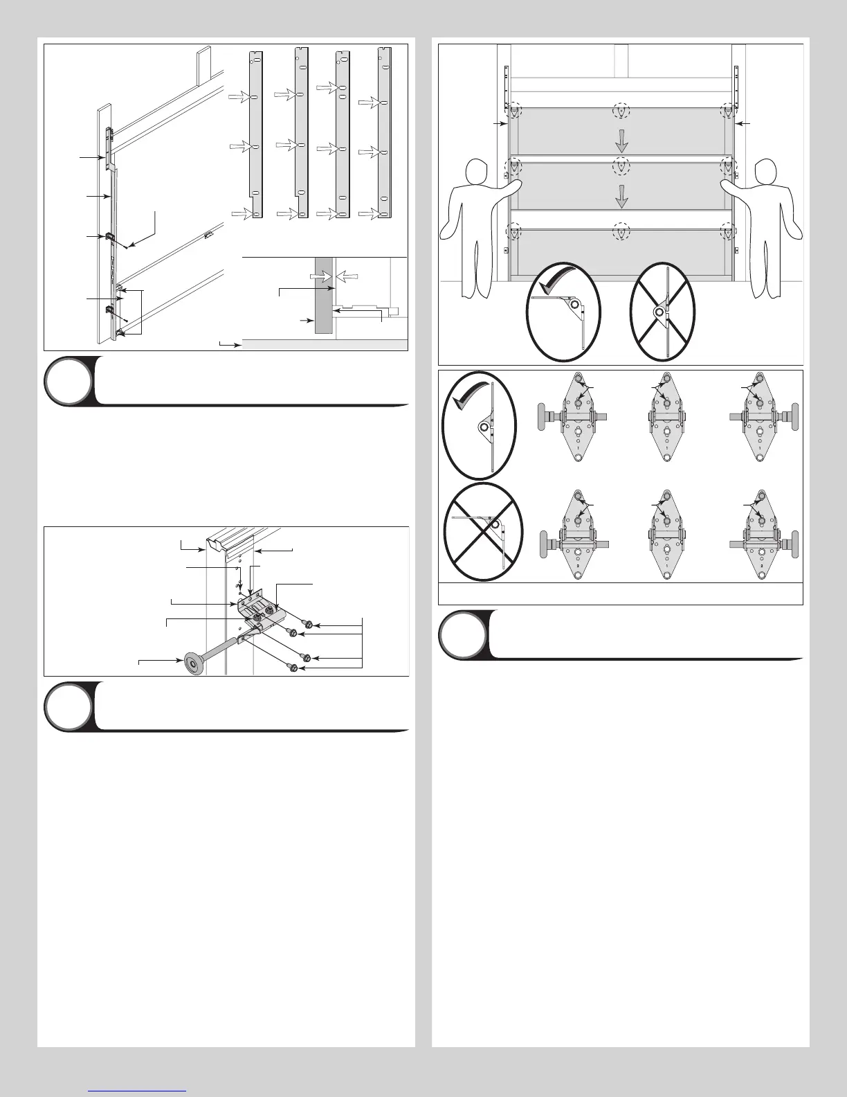
Stacking Sections
9
NOTE: The sections can be identified by the graduation of the installed graduated end hinges.
The smallest graduated end hinge on the section should be stacked on top of the bottom
section, with each graduated end hinge increasing as the sections are stacked, see door
section identification or Breakdown Of Parts.
NOTE: Make sure graduated end and center hinges are flipped down, when stacking another
section on top.
NOTE: Larger doors will use long stem track rollers with double graduated end hinges.
Place track rollers into graduated end hinges of remaining sections. With assistance, lift
second section and guide the track rollers into the vertical tracks. Lower section until it is
seated against bottom section. Flip hinges up. Fasten center hinge(s) first; then end hinges
last using 1/4” - 20 x 7/8” self-drilling screws.
NOTE: Larger doors with double graduated end hinges, fasten both hinges to connect the
sections using 1/4” - 20 x 7/8” self-drilling screws.
Repeat same process for other sections, except top section.
IMPORTANT: PUSH & HOLD THE HINGE LEAFS SECURELY AGAINST THE SECTIONS WHILE
SECURING WITH FASTENERS TO IT. THERE SHOULD BE NO GAP BETWEEN THE HINGE
LEAVES AND THE SECTIONS.
NOTE: Install lock at this time (sold separately). See optional installation step, Side Lock.
Intermediate
section
Lock
section
Vertical
track
Vertical
track
Center
hinge(s)
Left graduated end hinge
with short stem track roller
Right graduated end hinge
with short stem track roller
1/4”-14 x 5/8”
Self tapping
screw locations
NOTE: When placing the track rollers into the #2 graduated end hinges and higher, the track
roller goes into the hinge tube furthest away from the section.
1/4”-14 x 5/8”
Self tapping
screw locations
Self tapping
screw locations
Self tapping
screw locations
Stacking Top Section
10
Place the top section in the opening. Install a nail to prevent the top section from falling
backwards. Now, flip up the hinge leaves, hold tight against section, and fasten center hinges
first and end hinges last (refer to step, Stacking Sections). Vertical track alignment is critical.
Position flag angle or wall angle between 1-11/16” (43 mm) to 1-3/4” (44 mm) from the
edge of the door; tighten the bottom lag screw. Flag angles must be parallel to the door sec-
tions. Repeat for other side.
IMPORTANT: THE DIMENSION BETWEEN THE FLAG ANGLES OR WALL ANGLES MUST BE
DOOR WIDTH PLUS 3-3/8” (86MM) TO 3-1/2” (89 MM) FOR SMOOTH, SAFE DOOR OPERA-
TION.
FOR QUICK INSTALL TRACK: Complete the vertical track installation by securing the jamb
bracket(s) and tightening the other lag screws. Repeat for other side.
FOR FULLY ADJUSTABLE TRACK OR RIVETED TRACK: Complete the vertical track instal-
lation by securing the jamb bracket(s) and tightening the other lag screws. Push the vertical
track against the track rollers so that the track rollers are touching the deepest part of the
curved side of the track; tighten all the track bolts and nuts. Repeat for other side.
9