20
Please Do Not Return This Product To The Store. Contact your local Wayne-Dalton dealer. To find your local Wayne-Dalton dealer, refer to your
local yellow pages/business listings or go to the Find a Dealer section online at www.wayne-dalton.com
Tools Needed:
Tools Needed:
1-11/16” TO 1-3/4”
FLAGANGLE
TOP
SECTION
NAIL
ROLLER
VERTICAL TRACK
ROLLER AGAINST
VERTICAL TRACK
TOP SECTION
FLAGANGLE
(2) 1/4”- 20 FLANGE
HEX NUTS
VERTICAL TRACK
HORIZONTAL
TRACK
(2) 1/4”- 20 X 5/8”
CARRIAGE BOLTS
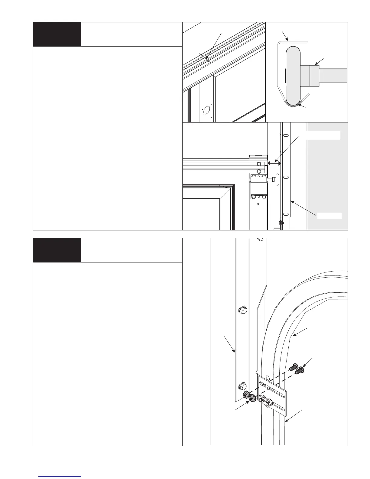
To install horizontal track, place the
curved end over the top roller. Align
the bottom of the horizontal track with
the vertical track. Hand tighten the
horizontal track to the flagangle with (2)
1/4”- 20 x 5/8” carriage bolts and (2)
1/4”- 20 flange hex nuts.
Level the horizontal track assembly and
bolt the horizontal angle to the slot in
the flagangle using
(1) 3/8”- 16 x 3/4” hex head bolt and (1)
3/8”- 16 hex nut. Repeat for other side.
Remove the nail that was temporarily
holding the top section in place,
installed in Step 12.
IMPORTANT: FAILURE TO REMOVE NAIL
BEFORE ATTEMPTING TO RAISE DOOR
COULD CAUSE PERMANENT DAMAGE
TO TOP SECTION.
13
9/16” Socket
7/16” Socket
Ratchet Wrench
9/16” Wrench
Level
Hammer
Flat Tip
Screwdriver
Attaching Adjustable Flagangle
to Horizontal Track
BETWEEN THE FLAGANGLES MUST BE
DOOR WIDTH PLUS 3-3/8” (86MM) TO
3-1/2” (89 MM) FOR SMOOTH, SAFE
DOOR OPERATION.
Complete the vertical track installation
by securing the center jamb bracket(s)
and tightening the other lag screws.
Push the vertical track against the
rollers so that the rollers are touching
the deepest part of the curved side of
the track (see illustration). Tighten all
the carriage bolts and nuts.
Repeat for opposite side.
Top Section Continued...