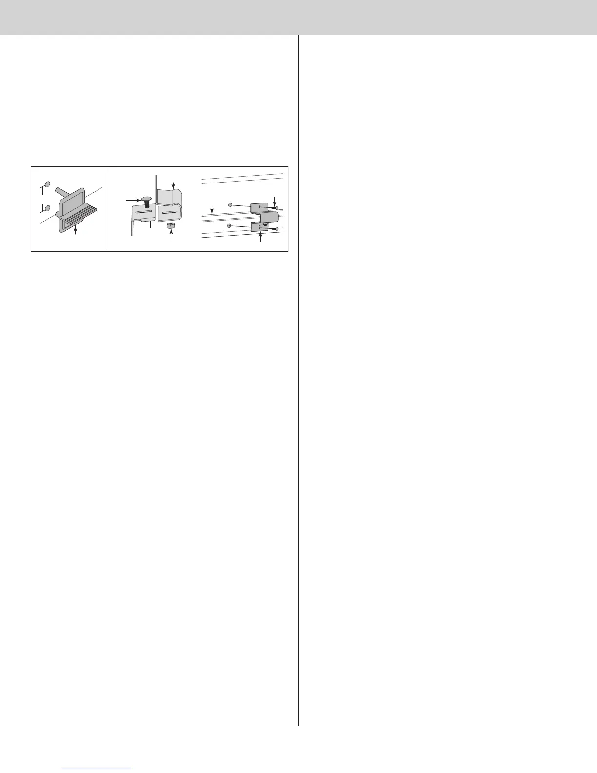
Make one mark 1” (25 mm) up from the center of bottom edge of the bottom section and
another mark 2-3/16” (56 mm) up from the first mark.
NOTE: Top of step plate can be no higher than 8” from the bottom of the door.
Drill a 7/16” (11 mm) hole through the section at each mark and insert the outside step
plate. Loosely fasten step plate slide to base with (1) 1/4” - 20 x 5/8” carriage bolt and nut.
Align inside step plate holes and fasten from inside using the #8 screws provided. Install one
#8 x 3/4” screw in the bottom step plate hole. The screw in the top hole varies with door
models. Use the screw size shown below for your model door.
a) #8 x 3/4” screw for model 9100
b) #8 x 1” screw models 9405/9605
Tighten 1/4” - 20 carriage bolt and nut.
Outside step plate
2-3/16”
1”
Bottom
section
Hex nut
1/4” - 20 x 5/8”
Carriage bolt
Step plate
base
Step plate
slide
Assembled inside step plate
#8 screw
Bottom
Section
Strut
14