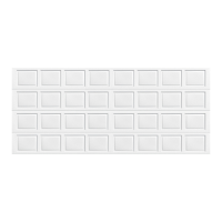
Long stem
track roller
Double
graduated
end hinge
(Hinge tube)
Bottom section
Counterbalance
lift cable
Short stem
track roller
Bottom corner
bracket
warning label
Bottom
weather seal
#1 Single
graduated
end hinge
(Hinge tube)
Short stem
track roller
Bottom
section
Counterbalance
lift cable
Bottom corner
bracket
1/4”-20 x 11/16”
Self drilling screws
1/4” - 20 x 11/16” Self
drilling screws (RED HEAD)
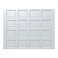
Positioning Bottom Section
3
Center the bottom section in the door opening. Level the section using wooden shims (if
necessary) under the bottom section. When the bottom section is leveled, temporarily hold it
in place by driving a nail into the jamb and bending it over the edge of the bottom section on
both sides.
Weather seal (If applicable)
Level
Bottom section
Wooden shims (If necessary)
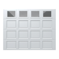
Vertical Tracks
4
NOTE: Depending on your door, you may have Quick Install Flag Angles, Fully Adjustable
Flag Angles or you may have Riveted Vertical Track Assemblies. Refer to Package Contents /
Breakdown of Parts, to determine which Flag Angles / Vertical Track Assemblies you have.
IMPORTANT: IF YOUR DOOR IS TO BE INSTALLED PRIOR TO A FINISHING CONSTRUCTION
OF THE BUILDING’S FLOOR, THE VERTICAL TRACKS AND THE DOOR BOTTOM SECTION
ASSEMBLY SHOULD BE INSTALLED SUCH THAT WHEN THE FLOOR IS CONSTRUCTED, NO
DOOR OR TRACK PARTS ARE TRAPPED IN THE FLOOR CONSTRUCTION.
IMPORTANT: THE TOPS OF THE VERTICAL TRACKS MUST BE LEVEL FROM SIDE TO SIDE.
IF THE BOTTOM SECTION WAS SHIMMED TO LEVEL IT, THE VERTICAL TRACK ON THE
SHIMMED SIDE MUST BE RAISED THE HEIGHT OF THE SHIM.
Starting on the left hand side of the bottom section, remove the nail. Position the left hand
vertical track assembly over the track rollers of the bottom section. Make sure the counter-
balance lift cable is located between the track rollers and the door jamb.
NOTE: Drill 3/16” pilot holes into door jamb for the lag screws.
Loosely fasten jamb brackets and flag angle to the jamb using 5/16” x 1-5/8” lag screws.
Tighten lag screws, securing the bottom jamb bracket to jamb, maintain 3/8” to 5/8” spac-
ing, between the bottom section and vertical track. Hang counterbalance lift cable over flag
angle. Repeat same process for other side.
Vertical
track
assembly
Jamb
bracket
Flag
angle
Flag angle lag screw locations
5/16” x 1-5/8”
Lag screws
Bottom
section
Track
rollers
12R FA
3/8” to 5/8”
Spacing
Bottom section
15R QI12R QI
Floor
Track roller
15R FA
Vertical track
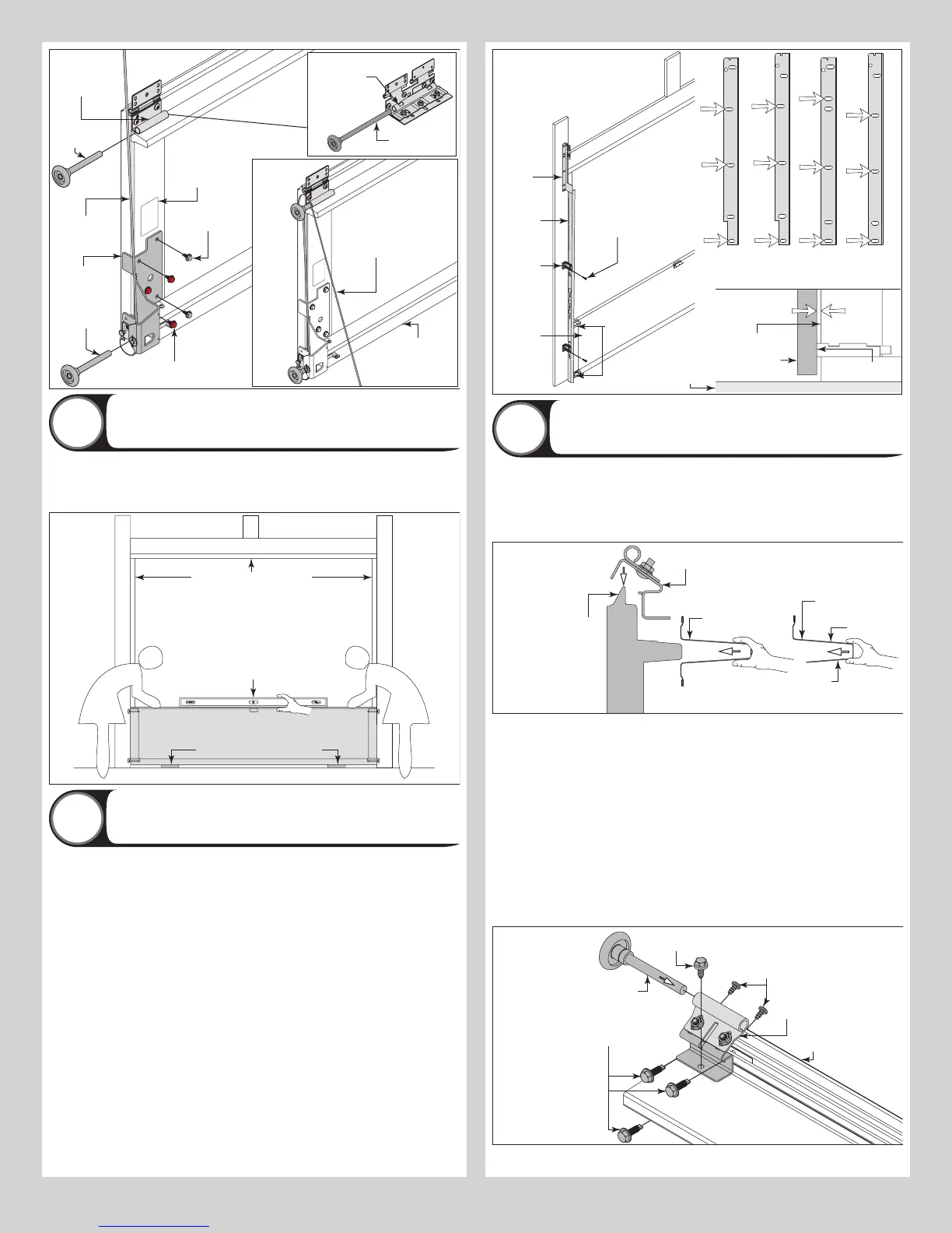
Attaching Top Fixtures To Top Section
5
NOTE: Depending on your door, you may have strut (U-shaped) or asymmetrical strut. Refer
to Package Contents / Breakdown of Parts, to determine which type of strut you have.
NOTE: The top fixtures come pre-assembled from the factory.
Place the strut (U-shaped) or the asymmetrical strut over the top rib of the top section, as
shown.
Strut
(asymmetrical)
(attached to top rib)
Long leg
Short
leg
Strut (U-shape)
(attached to top rib)
Top section
Top rib
Male
part of
top
section
Top fixture
assembly
Center the strut left to right on the section surface. Starting on the left hand side, locate the
edge of the top section and seat the top fixture on the male part of the top section, as shown.
Secure the top fixture assembly and the strut to the top section:
1. Attach one 1/4” - 14 x 5/8” self-tapping screw to the top fixture assembly.
2. Attach two 1/4” - 20 x 11/16” self-drilling screws to the top fixture assembly.
3. Attach two #12 x 1/2” phillips head screws on the opposite side of top fixture assembly.
Insert a roller into the top fixture slide, as shown. Repeat the same process for the other side.
NOTE: The top fixture slide will be tightened and adjusted later, in step, Adjusting Top Fixture.
NOTE: Ensure the top fixture slide is able to slide along the top fixture base. If needed, loosen
the 1/4” - 20 flange hex nuts.
IMPORTANT: IF YOU’RE SECURING AN ASYMMETRICAL STRUT TO THE TOP SECTION, IT IS
RECOMMENDED NOT TO INSTALL ANY FASTENERS INTO THE SHORT LEG OF THE ASYM-
METRICAL STRUT.
1/4” - 20 x 11/16”
Self drilling screws
Top section
Self tapping screw
#12 x 1/2” Phillip
pan head screws
Short stem
track roller
Top
fixture
slide
Strut
IF YOU HAVE A STRUT (U-SHAPED): Fasten each end of the strut to the end cap with (2)
7