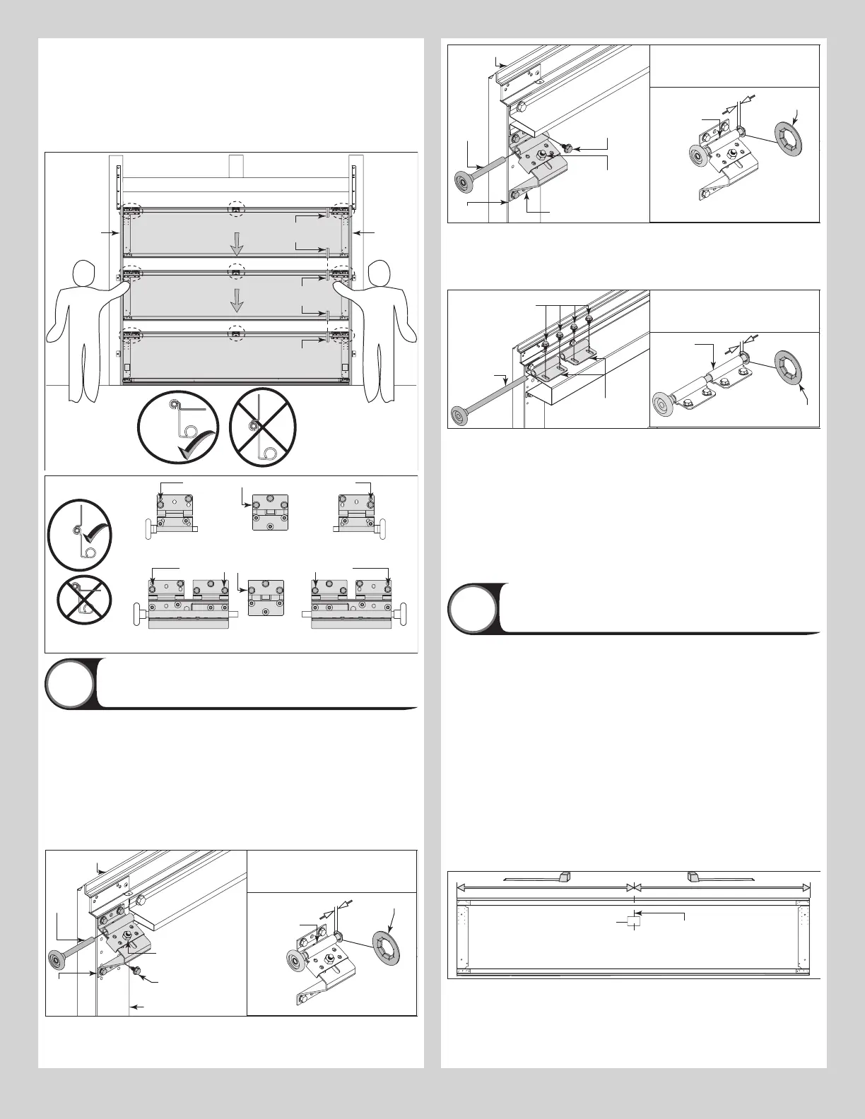
NOTE: Larger doors with double graduated end hinges, fasten both hinges to connect the
sections using 1/4” - 14 x 5/8” self-tapping screws.
Repeat same process for other sections, except top section.
IMPORTANT: PUSH & HOLD THE HINGE LEAFS SECURELY AGAINST THE SECTIONS WHILE
SECURING WITH 1/4” - 14 X 5/8” SELF TAPPING SCREWS. THERE SHOULD BE NO GAP
BETWEEN THE HINGE LEAFS AND THE SECTIONS.
NOTE: If applicable, refer to the Windload Specification Sheet to install the hinge brackets
along the bottom and or top portion of the section.
P/N # 327985 NEW 9-04-06P/N # 327985 NEW 9-04-06 P/N # 327985 NEW 9-04-06P/N # 327985 NEW 9-04-06 P/N # 327985 NEW 9-04-06
Lock section
Bottom section
Vertical
track
Alignment
sticker
Alignment
sticker
Alignment
sticker
Vertical
track
Center
hinge(s)
Center
hinge(s)
Left graduated end hinge
with short stem track roller
Right graduated end hinge
with short stem track roller
1/4”-14 x 5/8” Self tapping screw locations
1/4”-14 x 5/8” Self tapping screw locations
Left double graduated end
hinge with long stem track roller
Right double graduated end
hinge with long stem track roller
Attaching Top Fixtures To Top Section
9
NOTE: Depending on your door, you may have Top Fixture Assemblies or you may have Top
Fixture Roller Slides. Refer to the Windload Specification Sheet, Package Contents, Break-
down of Parts, to determine which Top Fixtures you have.
IF YOU HAVE TOP FIXTURE ASSEMBLIES: Referring to the Windload Specification Sheet
and using the illustrations below, determine if your top fixtures are supposed to be installed
next to the strut or installed below the strut. Starting on the left hand side of the top section,
place the top of the top fixture base onto the top section, as shown. Next, secure the top
fixture to the top section using (4) 1/4” - 20 x 7/8” self drilling screws. Loosen the 5/16” - 18
hex nut on the top fixture slide. The top fixture slide will be tightened and adjusted later, in
step, Adjusting Top Fixture. Insert a short stem track roller into top fixture slide. Repeat same
process for other side.
Short
stem
track
roller
Endcap
5/16” - 18 Hex nut
and 5/16” - 18 x 5/8”
Carriage bolt
Top
fixture
base
Strut
1/4”-20 x 7/8”
Self-drilling screws
1/2”
Top fixture
roller slide
Pushnut
NOTE: Refer to the Windload Specification
Sheet to determine if a pushnut is
required to be installed on each short
stem track roller, as shown.
Short
stem
track
roller
Endcap
5/16” - 18 Hex nut
and 5/16” - 18 x
5/8” Carriage bolt
Top fixture base
Strut
1/4”-20 x 7/8”
Self-drilling screws
1/2”
Top fixture
roller slide
Pushnut
Refer to the Windload Specification
Sheet to determine if a pushnut is
required to be installed on each short
stem track roller, as shown.
IF YOU HAVE TOP FIXTURE ROLLER SLIDES: Starting on the left hand side of the top
section and using the top fixture as a template (shown on the Windload Specification Sheet),
determine the placement for the top fixture roller slide on the top portion of the strut. Mark
and pre-drill the strut, as shown on the template. Fasten the top fixture roller slides to the
strut using (2) 1/4” - 20 x 7/8” self drilling screws. Repeat same process for other side.
Long stem
track roller
Top fixture
roller slides
1/4”-20 x 7/8”
Self drilling screws
Top
section
Strut
1/2”
Top fixture
roller slide
Pushnut
NOTE: Refer to the Windload Specification
Sheet to determine if a pushnut is
required to be installed on each short
stem track roller, as shown.
NOTE: Refer to the Windload Specification Sheet to determine if you have pushnuts.
If your door came with pushnuts, install them now by placing a pushnut onto the end of each
roller stem and sliding it towards the top fixture roller slide. Leave at least 1/2” of space
between pushnut and the top fixture slide.
NOTE: When positioning the pushnut onto roller stem, ensure the tabs on the pushnut are
pointing away from roller stem.
IMPORTANT: ACCURATELY POSITIONING THE PUSHNUT ONTO THE ROLLER STEM IS CRITI-
CAL. ONCE THE PUSHNUT IS PUSHED ONTO THE ROLLER STEM, THE TABS MAKING CON-
TACT WITH THE STEEL SURFACE WILL MAKE IT DIFFICULT TO REPOSITION THE PUSHNUT.
Refer to the Windload Specification Sheet and install the pushnuts onto the other roller stems
using the same process as above.
Attaching Drawbar Operator Bracket
10
NOTE: If you’re installing a drawbar operator, the drawbar operator bracket must be mounted
and secured prior to installing top section.
IMPORTANT: To avoid possible damage to your door, wayne dalton recommends reinforcing
the top section with a strut.
IMPORTANT: When connecting a drawbar operator type garage door opener to this door, a
Wayne Dalton operator/ drawbar operator bracket must be securely attached to the top sec-
tion of the door, along with any strut provided with the door. The installation of the drawbar
operator must be according to manufacturer’s instructions and force settings must be
adjusted properly.
Remove, but retain (4 - 6) 1/4” - 20 x 7/8” self drilling screws from the center of the strut,
allowing the drawbar operator bracket to slide between the section and the strut.
Locate the center of the top section and slide drawbar operator bracket under strut until the
drawbar operator bracket is seated against the strut flange.
NOTE: Prior to fastening drawbar operator bracket to top section, ensure the top edge of
drawbar operator bracket is aligned with the top edge of the section, as shown.
Attach the drawbar operator bracket using (8) 1/4” - 20 x 11/16” self drilling screws (as
shown). Finish re-attaching the strut using the self tapping screws removed previously.
Top section
Center line of
top section
Drawbar operator
bracket label
NOTE: For retro fit applications, the drawbar operator
bracket must be aligned with an existing drawbar operator.
10




 To Next Page